Chapter 7 - The Wing
Section 4 - Wing Internals
Flap Hinge Fabrication
The Flap system in the Super2 is quite sophisticated, but if the instructions are followed closely they are straight forward to fabricate and will perform excellent. The Flaps are designed so that up to about 15 degrees deployment there is no gap between the flap and the rear wing. But as the flaps progress to full 40 degree deflection a slot progressively opens between the flap and a slot in the aft wing allowing air to flow up and over the top flap surface. The Flaps at 10 degrees deployment is used to add lift to the wing with minimal drag. This mode is useful in takeoffs where extra lift is desired, but drag would be detrimental. This mode is also useful in slower precision flight such as an approach to an airport or instrument approach procedure. When the flaps are moved to 30 degrees down they add additional lift and produce a far amount of drag. The lift is created behind the CofG so the nose is tilted down, which is helpful in seeing over the nose on landing. With 40 Degrees of flaps, the desired landing configuration, maximum lift and drag are created and the nose is dropped even lower. The stall speed is the lowest in this configuration.
If one studies the geometry of the flap hinge system it will be noted that the axis that the hinges rotate around has some peculiar characteristics. It is located behind and below the leading edge of the flaps, but most notably it is not parallel to any wing structure. Therefore the alignment of the hinges cannot be simply referenced to the trailing edge. Also the flaps will not mount flat to the bottom of the wing or the rear spar. To allow proper alignment of the hinge system an alignment fixture has to be fabricated. More on this when we discuss the installation of the flaps.
Let us get started with the Fabrication of the flaps. Procure the required material:
- 1/8” sheet 6061T6 aluminum
- 6 feet of 1” X 1” X 1/8” 6061T6 aluminum Angle
- 6 each NAS75-3-004 Bushings
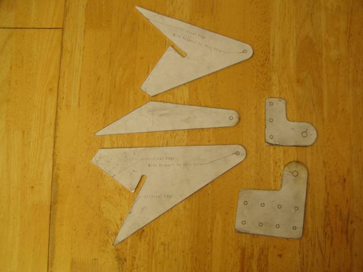
The first step is to print out the following flap drawing 1:1 templates and cut out the patterns. Print two of each A sized page as we need two of each part for each side of the wing:
The aluminum angle is cut as follows:
- 4 each inboard aft spar mounting angle – 2.5” long
- 4 each outboard aft spar mounting angle – 3” long
- 4 each inboard wing skin mounting angle – 4” long
- 4 each mid wing skin mounting angle – 4” long
- 4 each outboard wing skin mounting angle – 4” long
Rough cut the aluminum parts from the 6061T6 1/8” aluminum sheet.
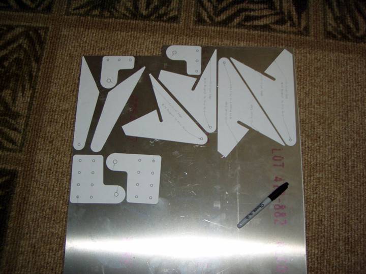
Cut parts from 1/8” 6061T6
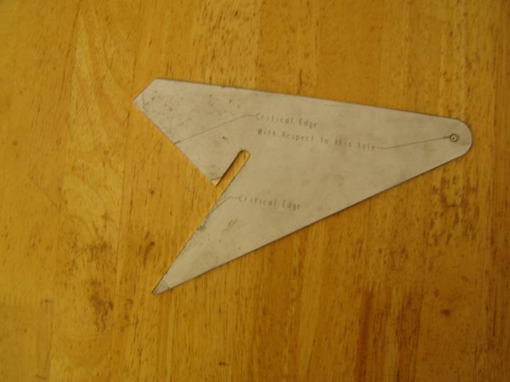
The flap hinge plates require the hinge point hole to be accurately placed with respect to the two edges shown on the print, so drill the hole and install the bushing before gluing the paper pattern in place and fabricating the part.
Practice installing the bushing on a scrap piece of aluminum of the same thickness. A drill bit and reamer are used to get the proper sized hole. Then the bushings can be pressed in with a hydraulic press, or if you are careful, you can tap the bearing in with a large flat punch and hammer.
Use a pilot punch and mark the location of the hole, remove the paper pattern, and drill the hole with a 15/64” drill bit. Finally ream to ¼”. Then press the NAS75-003-004 bushings in place. You will need 6 bushings.
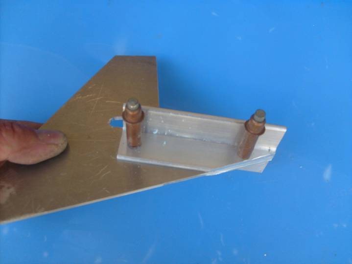
Bushing Pressed in Place
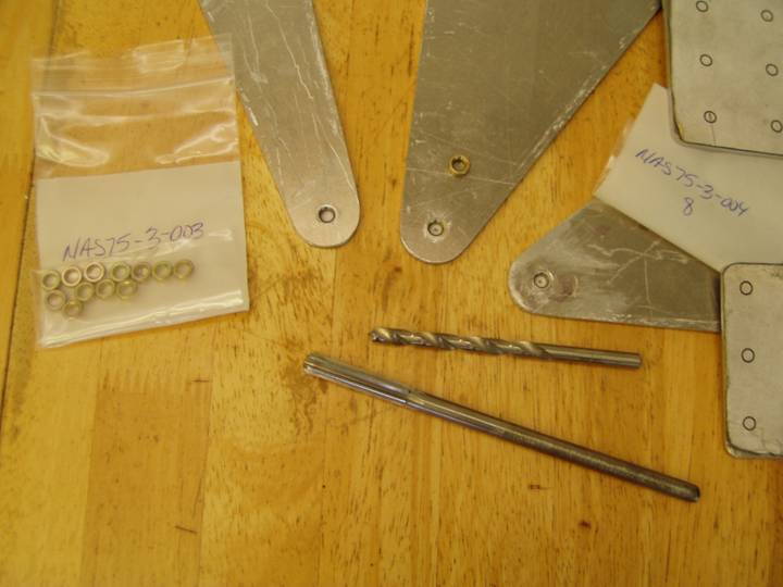
Tools Used to prepare holes for bushings (wrong sized bushings shown in photo)
Hold the hinge plate up to the light to align the hole in the bushing with the one printed on the pattern, then use a glue stick to adhere the pattern to the aluminum plate.
At this point finish the plates with the techniques you have learned in fabricating other aluminum parts.
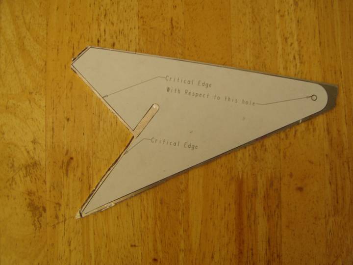
Pattern Adhered to Plate
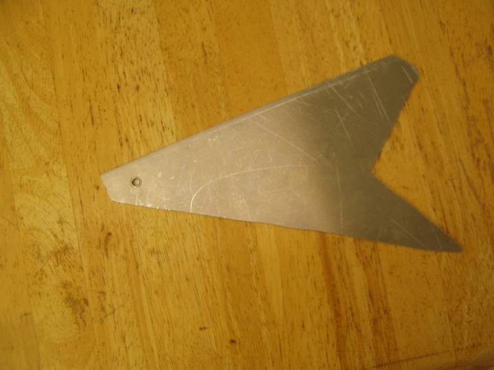
Finished Hinge Plate
A Complete Set of Hinge Plates
Next cut all of the angle to length.
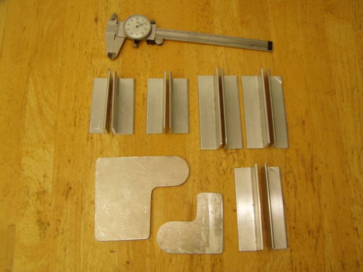
Aluminum Angles
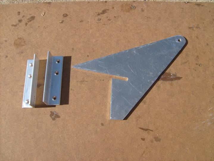
Let us start with the large outboard flap plate. Locate the outboard skin mounting angles which are 4” long. The angles will be mounted as shown in the following photo and need to be aligned exactly with out “critical edge” as shown in the print. The angle is positioned even with the end of the plate as shown.
Use a sharpie marker to mark where the angled edge of the hinge plate exposes the aluminum andgle as shown below. Cut this piece off. Prepare the second angle as you did the first.
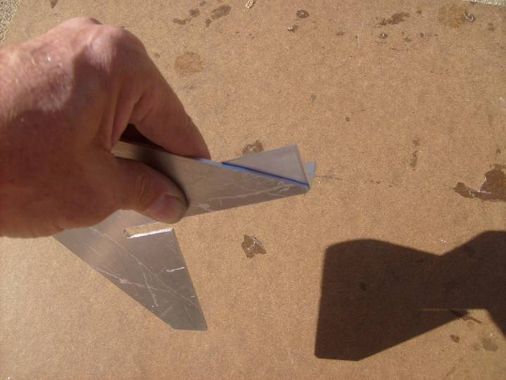
Proper Positioning of Angle
Firmly clamp the angles against the bottom skin edge of the plate, use the slot in the plate as a reference to insure you are clamping on the correct edge. Press the assembly against a flat surface to insure the angles are even, aligned with each other and aligned with the edge of the hinge plate.
Drill and cleco through the angle and the hinge plate.
Note: the following photos show holes drilled and countersunk for the hardware that holds the angle to the bottom skin. It is easier if this is done later to insure the holes are properly lined up with the flap reinforcement blocks and that the holes miss the rear spar.
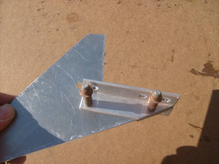
Angle Clecoed in Place
Angle Clecoed in Place
Angles clecoed to the hinge plate
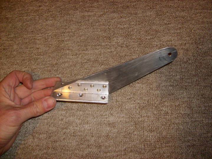
Drill, deburr and rivet the angles to the hinge plate with 1/8” domed rivets. Use 6 rivets alternating as shown.
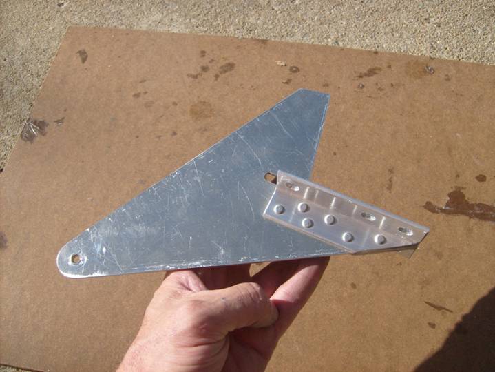
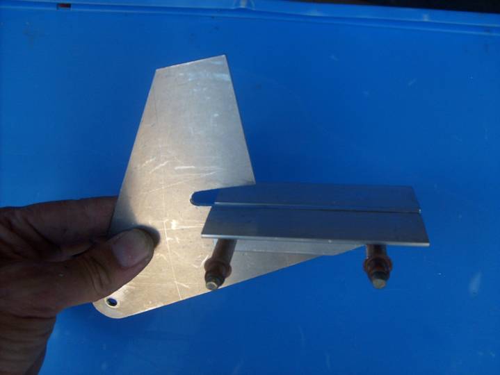
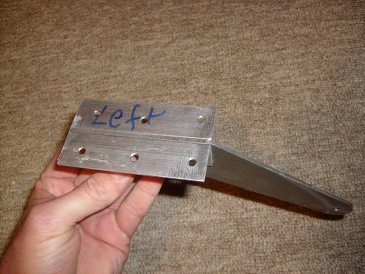
Completed Hinge Plate Assembly
Repeat this process with the inboard hinge plate again using 4” angles for the skin attatch edge.
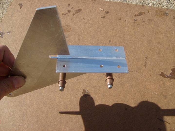
Angles Clecoed in place – Inboard hinge plate
Angles Clecoed in place
These holes are drilled later
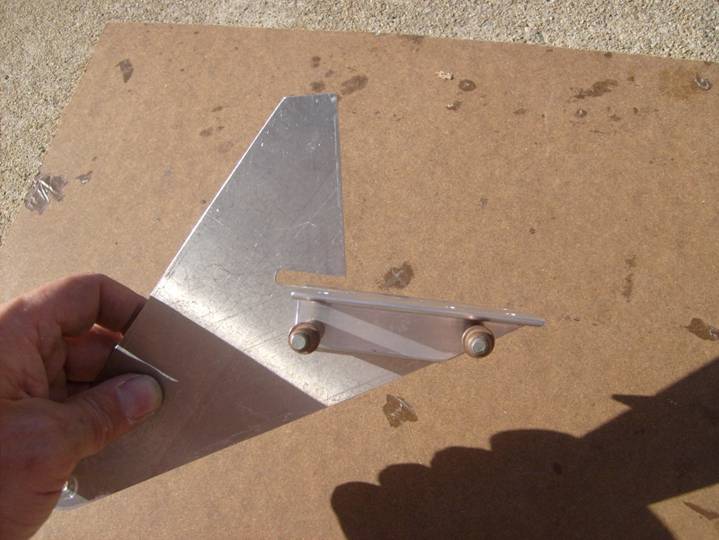
Finally, repeat the process on the center hinge support. This hinge bracket does not attach to the rear spar, only the bottom skin.
Completed Center Flap Hinge Plate Assembly
Completed Center Flap Hinge Plate Assembly
Complete.