Chapter 7 - The Wing
Section 1 - Spars
Main Spar Construction
We will use a moldless construction technique to build the main spar; all we need is a relatively flat surface such as a garage floor. We will start with a 24” X 96” sheet of 4.5 lb. last-a-foam and cut two long strips, bonding them end-to-end. This will become the foam core of our spar. We will install phenolic hard points where the spar mounts to the fuselage and again where the outboard spars attach. The primarily shearweb will be laid up over both sides of this foam core. At this point we will measure out lengths of our graphlite carbon fiber and bond them together to form our spar caps. Foam will be removed from the top and bottom edges of the spar as was done in the fabrication of the outboard spars and we will install the primary spar caps.
We will then bond the lengths of carbon fiber graphlite to form the four secondary sparcaps. Two each will be mounted on top of the spar and two each will be mounted on the bottom of the spar. Finally we will layup the secondary shearweb over these caps creating a monolithic spar assembly.
Let us get started.
Cut a 96” length of ½” last-a-foam 13” wide. Make sure the edges are dead straight. Make a diagonal cut lengthwise 6” on one side 7” on the other.
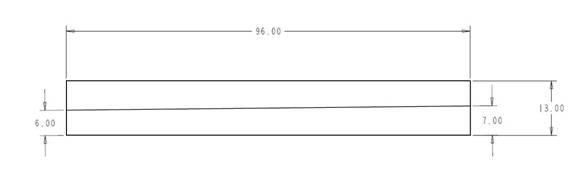
Rectangular ½” Last-a-Foam Stock
Place the 7” edges together other and tip the ends upwards. Use a laser level to draw a line between top corners of the outside tips and drop the center 3.5” for dihedral. See the drawing below.
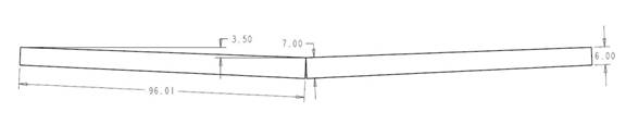
Put smaller ends together and tip up ends for dihedral
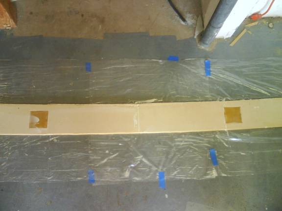
Next, trim the two pieces at the center to mate cleanly. Micro the joint. Measure 21” outward from center to each side. Now we need to create a smooth, curved transition between the two sides of the spar. This transition is created by removing a little material from the bottom center section of the spar, and adding a little material to the top middle section. See the following photo. Remove .33” from bottom center and smooth to blend at 21” on each side. Add foam to the top edge between 21” to 21” on each side rising .41” in center and also blend into a smooth curve.
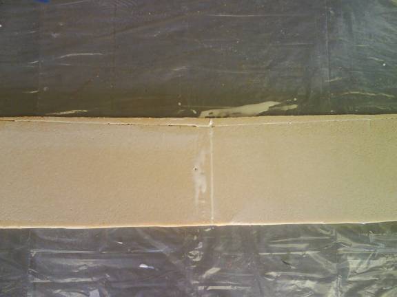
Center Spar Joint – material added on top, removed from bottom
Cut six squares of ½” thick phenolic. Measure outward from the center of the spar and center the blocks up and down and at the points measuring 17.5”, 76.25”, 93.875” from the center. The outboard hole is about 2” from outside edge. Rough up the phenolic blocks with coarse sandpaper as you did with the outboard spar blocks and install them with thick micro.
Center phenolic Blocks Installed
Outboard phenolic Blocks Installed
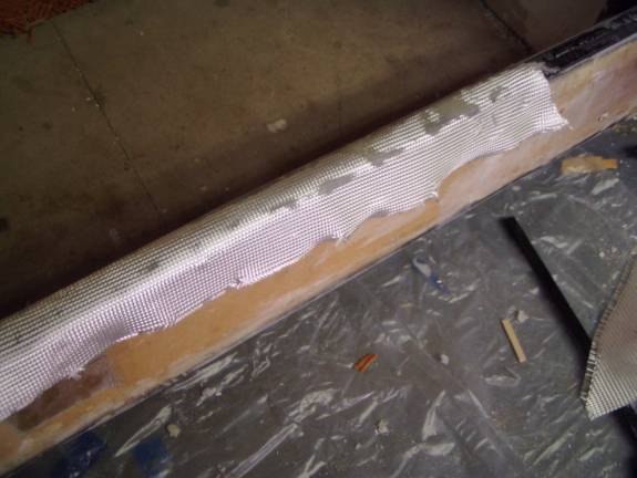
Ready to layup Primary Shearweb
We are now ready to install the primary shear webs. Mark the spar front and back as each side has a different layup schedule. On the front side of the spar mark 31 inches from the center on both sides and 66 inches from the center on both sides. The front of the spar will have five layers of BID fiberglass installed on the 45 degree bias. The first layer will run from 31 inches on one side to 31 inches on the other side. The second layer will run from 66 inches on one side to 66 inches on the other side. Finally, layup three additional layers over the entire length of the front side of the spar. Refer to the following table for the layup schedule for the primary shearweb.
Layer 1st
Front 1st Rear
1 31” 57”
2 66” entire
len.
3 entire
len. entire
len.
4 entire
len. entire
len.
5 entire
len.
Be sure to use a layer of peel ply over the final layup as we will be adding a secondary shear web structure later.
Repeat this process on the back side of the spar using the Rear layup schedule in the table above. The rear shearweb has only 4 layers of fiberglass BID.
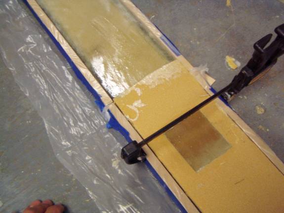
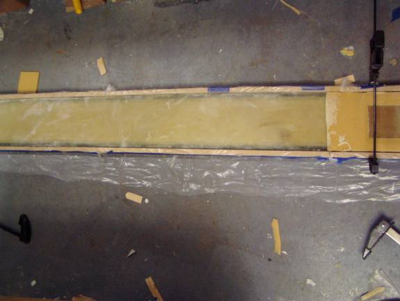
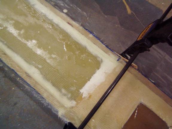
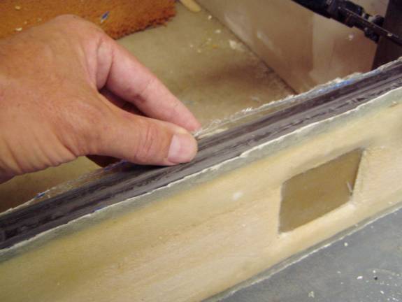
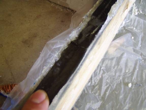
Once the epoxy has cured, remove the peel ply and carefully trim the front and rear shearwebs to the exact size of the foam. Clamp a straight edge to the spar to insure a nice straight, clean trim job.
Trimming shearweb to match foam
Trimming the primary shearweb to the foam edge
It is now time to fabricate the sparcaps. There will be primary and secondary sparcaps. You can fabricate them all now or fabricate them as needed. I prefer to fabricate all six caps at once. The caps are refered to as: the primary top, primary bottom, secondary front top, secondary rear top, secondary front bottom and secondary rear bottom.
The spar caps are made from varying lengths of our carbon fiber graphlite material. All of the sparcaps for the center wing spar are symmetrical about their center point. That is, mark the center of all of the individual lengths of graphlite and they will line up to form the center of the completed, bonded spar cap.
Refer to the following table and cut the necessary lengths of graphlite for the two primary spar caps. Each is composed of six lengths. Be very careful when handling and preparing the sparcaps. The graphlite material is easily cut with a pneumatic cutoff wheel and should be sanded with 100 grit sandpaper and cleaned with acetone before bonding. Use gloves and a respirator when performing these tasks in a well ventilated space. I do this outdoors dressed in protective gear. Be very careful when handling the graphlite as tiny slivers of the material can come loose and create splinters. Do not breathe carbon fiber dust, once in the lungs, it never comes out.
The spar caps are made by bonding the six lengths together using the bottom curved surface of the foam spar as a mold. The longest is placed against the foam spar first, followed by progressively smaller lengths. This way the natural springiness of the material will hold the strips together while they cure. A thin film of epoxy is used to bond them together. Use a sheet of plastic to protect the spar while the sparcaps are curing. As mentioned before, it is preferable to fabricate all six sparcaps at this time. Refer to the table further down the page for the length of graphite used in the secondary spar caps.
Make primary caps.
Length bott
cap top
cap
1 138 152
2 156 168
3 176 184
4 192 192
5 192 192
6 192 192
Using the spar as a mold for the sparcaps
Using the spar as a mold for the sparcaps
Once the sparcaps are cured, sand them to remove excess epoxy residue and create a rough surface for bonding to the spar. Again exercise extreme caution to avoid carbon fiber dust.
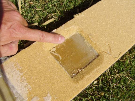
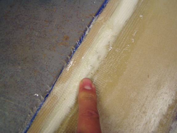
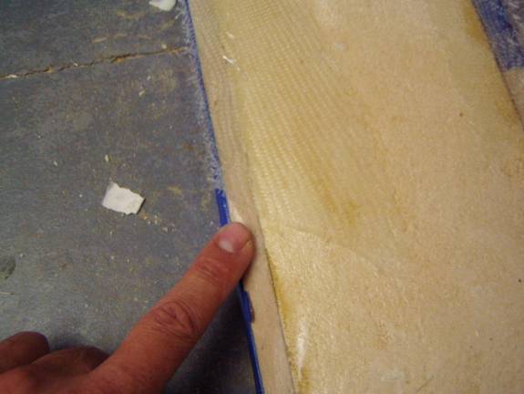
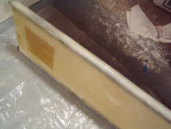
Lay the top and bottom spar caps into approximate position and mark the amount of foam that needs to be removed from the top and bottom edges to bury the sparcaps. The spar caps should end up being even or just below the trimmed shear web edges. Review the following two photographs to get an idea of the desired pocket you want to create.
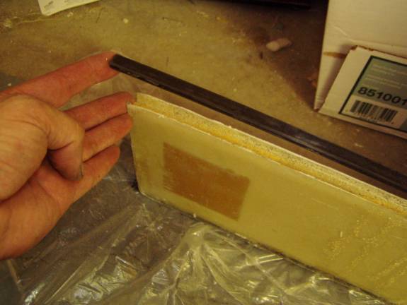
Foam removed for sparcap
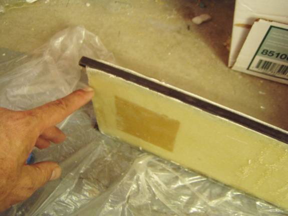
Test Fit Sparcap
Sparcap ready to be bonded in place
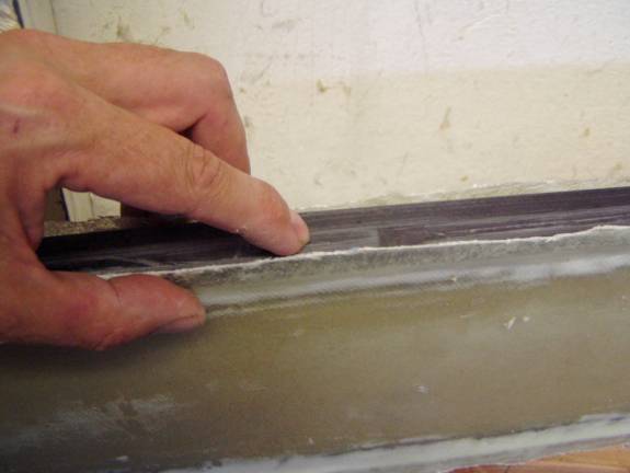
Once you have removed just enough foam and test fit the spar cap into the resulting pocked you are ready to bond it into place. Insure that you do not mix the spar caps up. The top cap is thicker than the bottom cap as Graphlite is slightly stronger in tension than compression.
After building the outboard spars you are well prepared and understand the techniques involved in installing the spar caps. We will create a flox mixture and lay down a bead of it into the slot created between the two shearwebs. We will then pour some epoxy resin down on top of the flox and press the spar cap into place. The flox mixture should ooze up the sides of the sparcaps and you need to work out all of the air under the caps. Then clamp the sparcap into position at or just below the edges of the shearweb. Clean up as much overflow epoxy as you can, it is much easier to do it now as opposed to waiting until after it has cured. Let cure.
Sand the top of the spar so the shearweb and sparcaps make a clean transisiton. Trim the shearweb if required.
Now flip the spar over and install the bottom spar cap in the same manner.
Congratulations you have completed the primary shearweb and primary sparcap installations. Now we will move on to the secondary caps and secondary shearweb fabrication.
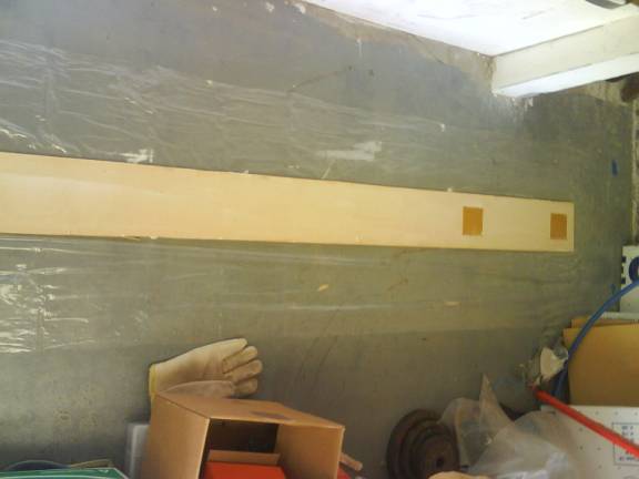
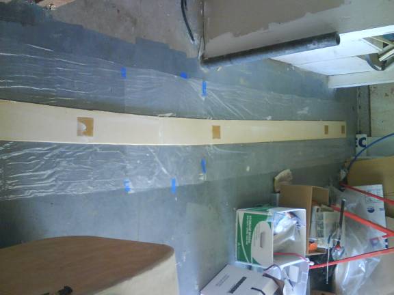
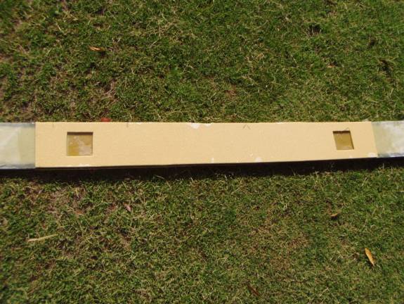
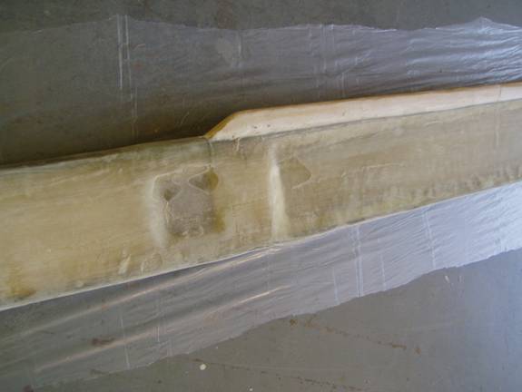
Bond 48” length of ¼” last-a-foam to both sides of the center section of the spar as shown in the following photos. Remove the foam over the phenolic hardpoints and then trim the foam to a bevel around the hardpoints. Trim the foam to match the shape of the top and bottom of the spar. Refer to the following photos.
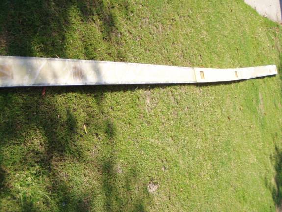
Primary sparcaps installed
Center foam installed
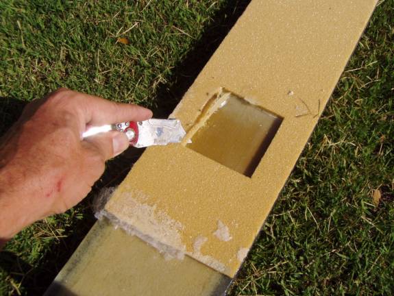
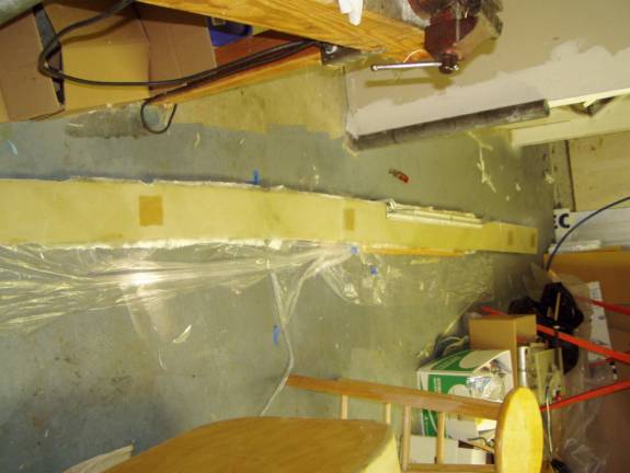
Bevel foam around phenolic hardpoints
Bevel foam around phenolic hardpoints
The secondary sparcaps are installed next. The secondary sparcaps are twice as wide as the primary sparcaps and are made from two sets of bonded strips of Graphlite Carbon fiber. If you have not fabricated your secondary spar caps yet, do so now. The spar is still easily used as a mold to shape the four spar caps.
Top Front secondary spar cap is 140 inches long, Top Rear Secondary sparcap is 126 inches in length, Bottom Front Secondary sparcap is 124 inches in length and the Bottom Rear Secondary spar cap is 108 inches in length. Use the following table to fabricate the four secondary spar caps as was done with the primary sparcaps. Top Front secondary spar cap is made from 5 strips of Graphlite, Top Rear Secondary sparcap is made from 5 strips of Graphlite, Bottom Front Secondary sparcap is made from 4 strips of Graphlite, and the Bottom Rear Secondary spar cap is made from 3 strips of Graphlite. The spar caps are symmetrical about their center as were the primary sparcaps.
Make secondary caps
Top
primary |
front |
rear |
152 |
56 |
46 |
168 |
74 |
64 |
184 |
94 |
84 |
192 |
116 |
104 |
192 |
140 |
126 |
192 |
|
|
Bottom
| 138 | 48 |
58 |
156 |
70 |
82 |
176 |
94 |
108 |
192 |
124 |
|
192 |
|
|
192 |
|
|
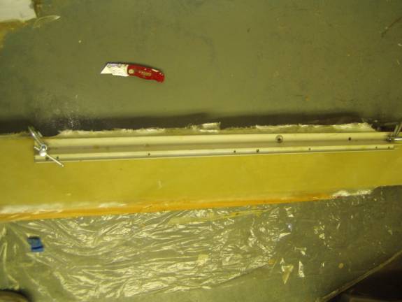
Next we need to make a pocket for the secondary sparcaps. I used strips of MDF clamped to the top and bottom of the spar measuring 1 inch wide and ½ inch tall. These were tightly wrapped in plastic to act as a mold release.
The center section of the spar is already one inch wide and a smooth
transition to the sparcap pockets is easy. The outboard sections
of the spar is only 1/2 inch thick and we need to us a thick micro
to create a radius under the MDF strips so the secondary shearwebs
can make a smooth transition from the ½ inch thick spar to
the 1 inch thick secondary sparcaps. Review the following
photos.
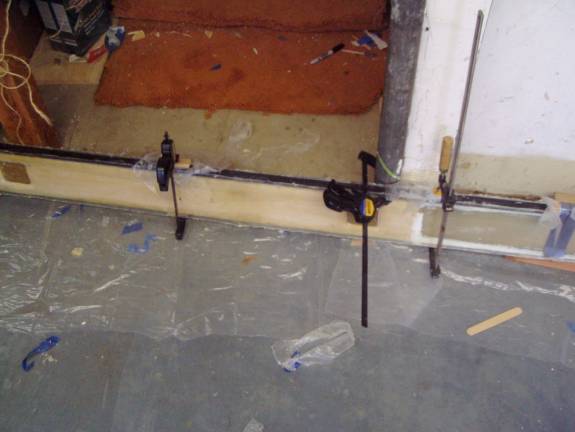
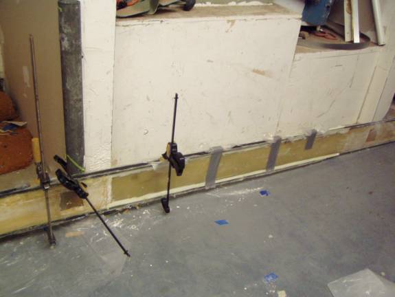
Clamp wood strips in place for sparcap pocket
MDF Strips clamped to form sparcap pocket
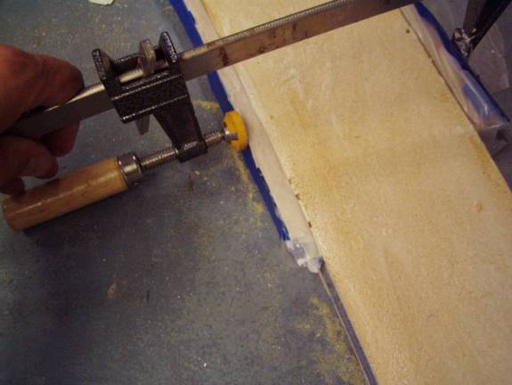
MDF Strips clamped to form sparcap pocket
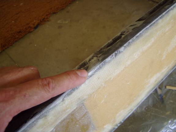
Use two layers of BID to create the sparcap pockets. Refer to the table above that defines the secondary spar cap lengths. No need to make the sparcap pockets run the total length of the spar, only put them where the spar caps need them. The fiberglass should extend about an inch and a half onto the spar and cover the ½” deep wooden strips. Once the fiberglass has cured trim the edges to the height of the wooden strips and then remove them.
Micro radius
Another view of the Micro radius
Pocket at mid spar
When you have formed your secondary sparcap pockets, test fit the sparcaps. Remember to place them in the correct orientation, there are four distinct sparcaps and each must be in the proper place.
Test fit secondary sparcaps
Test fit secondary spar caps
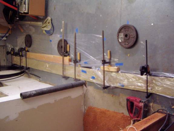
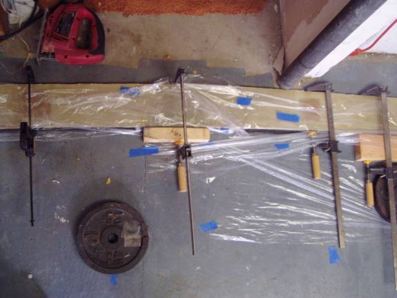
Once you are happy with the fit and orientation of the secondary spar caps bond them in place as you did the primary spar caps. Use plenty of epoxy and let it ooze out. This is no place to skimp on resin. Clamp the sparcaps in place and let them cure.
Secondary Sparcaps clamped in place
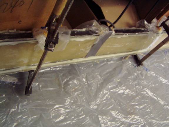
Secondary Sparcaps Curing
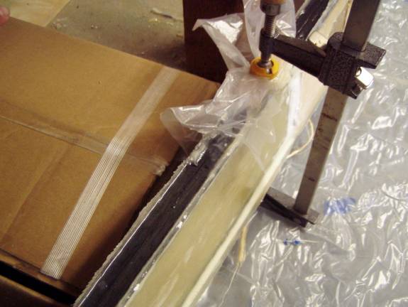
Note the Flox and Resin oozing between the sparcaps and shearweb
Clamps and duct tape secure spar cap during cure
Note excess Flox and resin post cure
After cure, Sand down shearweb to top of sparcap
Once the sparcap is bonded in place, grind down any excess flox and resin that may be standing proud of the sparcaps. Grind the shearwebs and sparcap pocket to match the height of the sparcaps. Do not grind into the graphlite
We now are going to seal the sparcap and create a nice radiused top surface for the secondary shearwebs to bond to.
Mix up a batch of flox and epoxy resin and create a layer over the sparcap. It does not need to be thick, only a 1/16 of an inch, but it must cover the sparcap and fill in any transition points between various graphlite rod pieces. See the next photo.
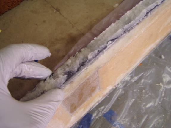
Flox spread over top of sparcap
Next layup a single BID layer over the Flox and smooth out all air and create a nice radius. The BID should extend a couple of inches down on each side of the spar as shown in the following photo. Use excess resin in this step, then use paper towel to remove the excess. We are striving for a nice smooth radiused top to the spar and absolutely no air bubbles or voids in the sparcap structure. Work the Flox out under the glass to create an even distribution side to side.
Fiberglass applied over the flox
The above picture shows a strip of fiberglass applied over the wet flox. I found that a better approach to applying this BID was to presaturate the cloth on a piece of plastic first. Wet the sides of the spar with resin using a paint brush, then apply the BID over the top of the spar. This way the fiberglass cloth is wet out better.
The finished encapsulation of the sparcap
Notice in the above picture how even the flox is distributed under the BID cloth and how there is a noticeable radius to the top of the spar. This will make the application of the secondary shearweb much easier.
Next add reinforcement strips over all of the phenolic hardpoints. The four outboard hard points get two layers of BID, the first will be 4 inches wide and the second will be 5 inches wide. These will extend beyond the sides of the phenolic and wrap around the top of the spar. The spar is flipped over and the procedure is repeated on the other side with the BID being wrapped around the bottom of the spar and over the reienformcent on the other side. The two inboard hardpoints get 4 reinforcement layers of BID, each 1 inch wider than the last and extending ½ inch further on each side. These likewise wrap over and under the spar. This helps transfer the forces from the shearweb to the spar caps.
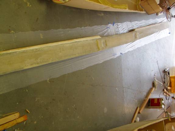
Finally the secondary shearwebs are laid up. These are very similar to the primary shearwebs with the exception that they overlap the sparcaps. The shearweb is installed from the bottom of the existing shear web, up the side, over the top and extending down the other side about two inches. Then the spar is flipped over and the other side’s shearweb is laid up, again from the bottom of the existing shear web, up the side, over the top and extending down the other side about two inches. This way the entire spar is encapsulated in the BID creating the secondary shearweb.
The shearwebs are made up of 4 layers of BID, two partial length layers and two full length layers. The first layer extends 50 inches each side of the middle of the spar and the second layer extends 80 inches both sodes of the spar. Lay up the two partial length layers first, cover the layup with peel ply and let cure.
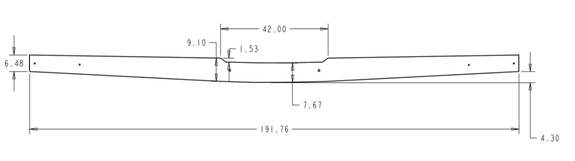
A sparcap extension is added to the top of the spar. This is fabricated from a strip of ½ inch last-a-foam. Below is a drawing of the completed spar just to give an idea of the finished product. The spar cap extension begins 19 inches from the center of the spar, rises to its full height at 21 inches from the center of the spar and then tapers to zero height at the spar tip. The height of the extension at 21 inches from center is about 1.5 inches tall. Your height may vary but we are shooting for a spar height of just under 5.5" at the tip and 9 inches at the tallest point, 21 inches from the center.
Once this extension is bonded to the top of the spar, micro is used to fill in all empty spaces between it and the top spar caps.
Finally, two additional layers of BID are added to the shearweb on both sides of the spar, wraping around the top and bottom as was done with the two partial secondary shearweb layers.
This completes the main spar construction. We still need to orient and drill the mounting holes for both the outboard spar sections and the fuselage mounting holes. We will do this next. Congratulations on the completion of a major subassembly of the Super2.