Chapter 7 - The Wing
Chapter 2 - Ribs
Rib Features
Once all of the foam edges are prepped we will install the flanges. ONLY INSTALL FLANGES ON THE TOP EDGE OF THE RIBS. We do not need flanges on the bottom as we will install the bottom skins directly to the wing ribs without flanges. The flanges will run from about an inch and a quarter from the very front edge of the ribs all the way to the back edge. The flange can be about a half of an inch shy of the main spar. The depth of the flanges should be 3/8”. We will use ½” foam to sheet the wings and will remove about an 1/8” as we sand to shape.
Refer back the horizontal stabilizer rib construction on the use of flexible flanging tools to create the flanges. Mark a pencil line 3/8” from the edges first to give yourself a reference in case a flanging tool lifts or separates from the desired depth. Mark both the top and bottom of the ribs. We will only install flanges on the top of the rib, but we will use the marked lines to properly position the bottom skin as well. Some ribs will receive additional attention before we proceed with wing assembly, below is a summary:
- Rib A – the most inboard rib will only receive a flange on the top outboard edge. We will also pencil a line along the top and bottom outboard edges 3/8” from the edge. This rib will support the fuel sending unit so a mounting hole will be fabricated including a sealed nut plate. This rib has a large hole behind the spar that allows the aileron control tube to pass through.
- Rib B – this is a special rib and will be discussed in its own section. It is fabricated with a combination of phenolic, plywood and foam. It will have flanges on both sides of the top edge and mounting holes for the main gear leg.
- Rib BB – this is a special rib and will be discussed in its own section. It is fabricated with a combination of phenolic and plywood. It will have flanges on both sides of the top edge and mounting holes for the main gear leg as well as mounting holes for the aileron idler assembly.
- Rib C – this rib has several holes through it, some to vent the fuel, one is a fuel slosh gate and the one behind the spar is to allow the aileron control tube to pass. This rib will have flanges on both sides of the top edge. Mark both sides, top and bottom 3/8” from the edge with pencil.
- Rib D – This rib is the outboard rib of the center wing section and only has a flange on the top inboard edge. Mark this edge and the lower inboard edge with pencil. This rib also has a mounting area for the aileron belcrank and and outboard spar mounting point. This rib is mounted to the end of the main spar and has a large slot sized hole to allow the outboard spar to pass through.
- Rib E – This rib is the inboard rib of the outer wing section and only has a flange on the outboard top edge. Mark this edge and the bottom outboard edge with pencil 3/8” from the edge.
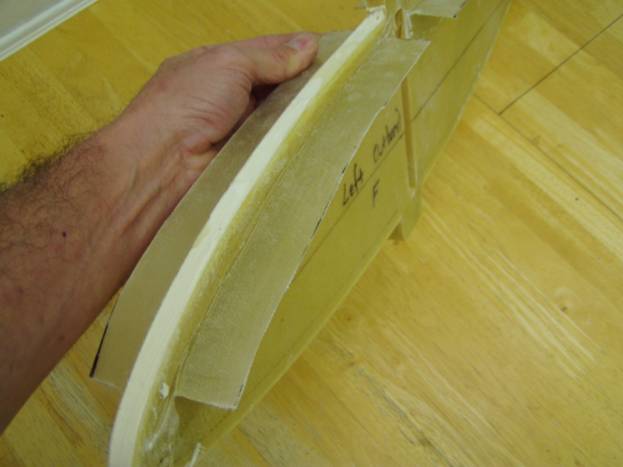
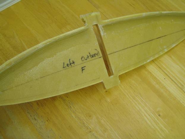
- Rib F – This is the center rib in the outboard wing section and will require a flange on both sides of the top edge. Also mark the bottom edge.
- Rib G – This is the outboard most rib and is bonded to the end of the outboard spar. It will require a flange along the top inboard edge. Also mark the bottom inboard edge.
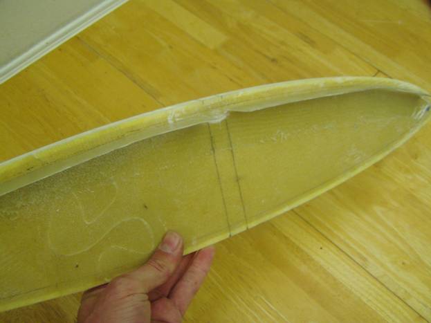
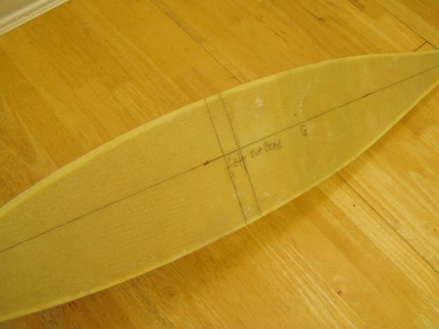
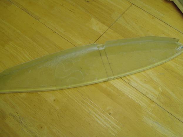
Rib Detail – Rib A
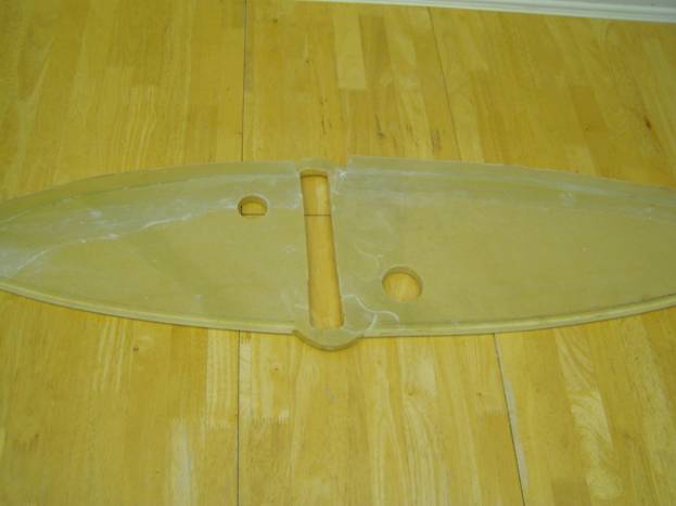
Outboard View of the Left A rib
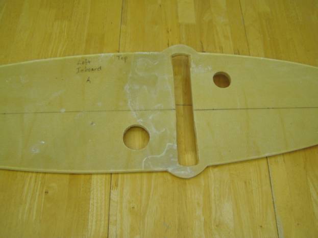
Inboard View of Left A rib
Once the flange is installed on the Outboard top side of the A rib and the aileron tube hole has been sealed with micro, we can install the feature that attaches the fuel sender. We will use the Stewart Warner ISS Fuel Senders used in RV kits and are available at Aircraft Spruce and Wicks. Aircraft Spruce Part number: 10-01101.
We will start with a 4 layer laminate and model it after the included rubber gasket in the kit. This will become a bond on nut plate installed on the outboard side of the rib.
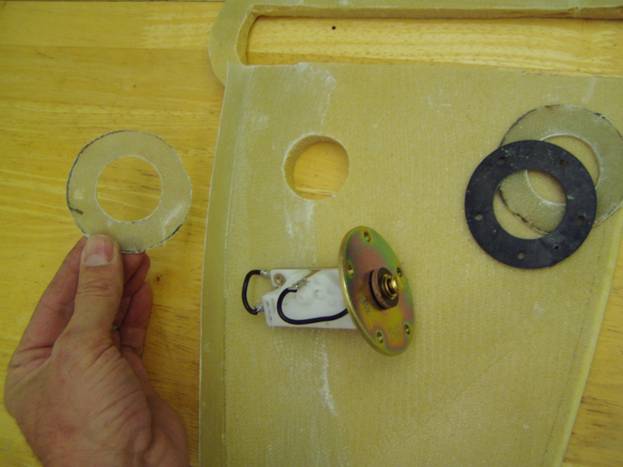
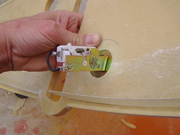
Sending unit components
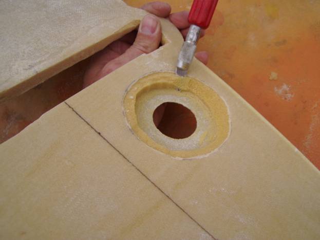
To prepare the rib to accept the sender, use a pencil to draw a circle on the inboard side of the rib, 3.5” in diameter and concentric with the fuel sender hole (the one on the top, front side of the spar).
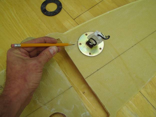
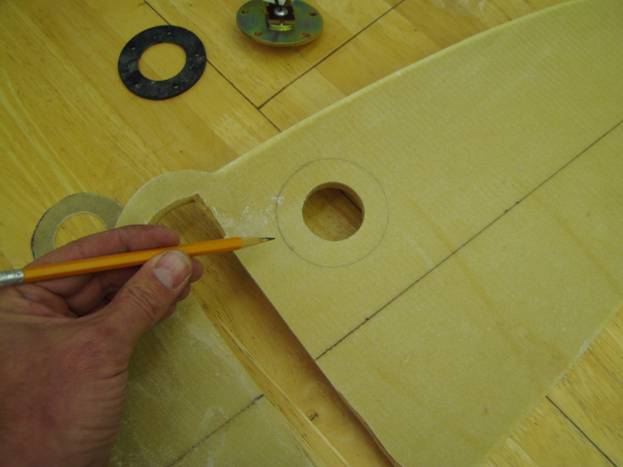
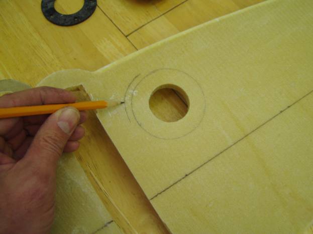
Carfully cut away the outside glass laminate. Insure you are working on the inboard side of the rib. Then lay the fuel sender into the hole and trace around the metal mounting plate
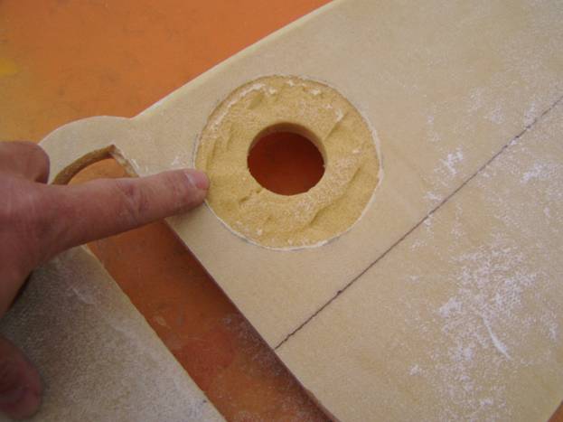
Remove the foam along this inside circle and insure that the sender fits inside the hole against the opposite glass skin. Now bevel the remaining foam to make a smooth transition from the inboard edge down to the opposite surface.
Slurry and apply a single layer BID over the foam to seal it. Apply a single layer BID on the outboard side of the rib extending and inch and a half around the hole as well.
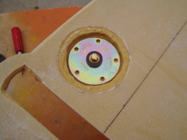
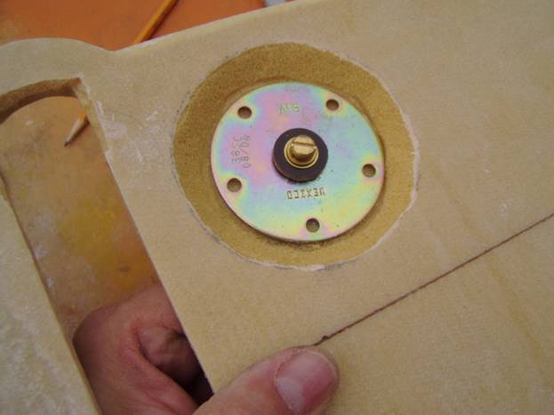
Outboard view of the fuel sending unit in A rib
Orient the sending unit in the hole as shown above with the sender pointing up. Drill the 5 mounting holes though the rib. Use a Cabosil epoxy mixture or structural adhesive to bond the nut plate in place. Use mold relase on the screws and be careful not to get any epoxy in the nut plates or on the screws. Once cured, remove the sender and screws. Cover the outside of the nut plate with a ring of ½” foam approximately the same shape as the nutplate. Sand it round, slury it and cover with a single layer of BID.
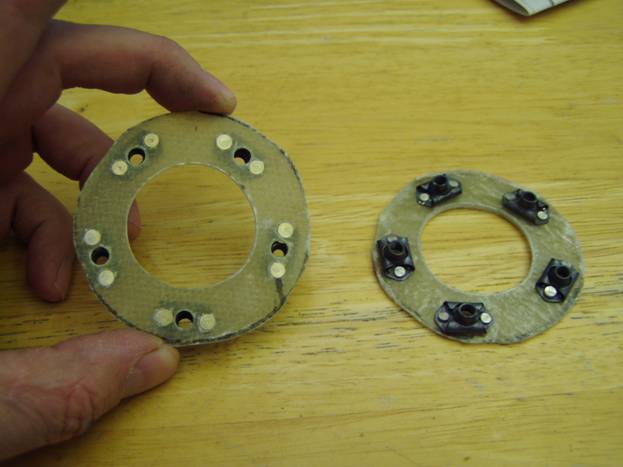
Fuel Sender Nut Plates
Rib Detail front B Rib-
this rib has several holes through it, some to vent the fuel, one is a fuel slosh gate and the one behind the spar is to allow the aileron control tube to pass. This rib will have flanges on both sides of the top edge. Mark both sides, top and bottom 3/8” from the edge with pencil.
Need picture of C rib
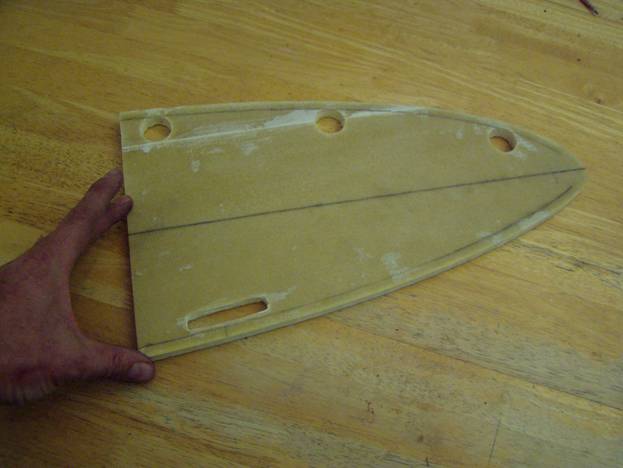
Rib D – The D rib will have a flange on the top inboard edge.
Inboard Top Flange on D rib
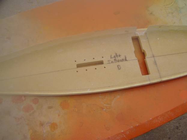
Outboard side of D rib
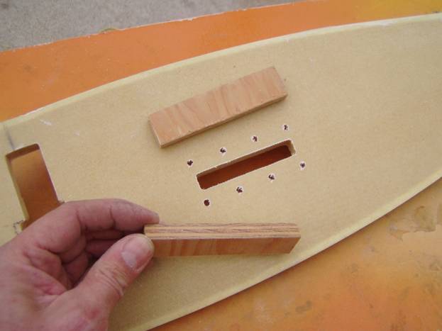
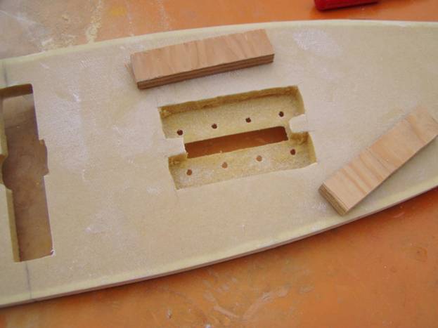
We will reinforce the D rib aileron bellcrank attaches points. Cut two pieces of ½” marine plywood 1” by 4”. Measure and mark the area and then remove a 1” X 4” section of fiberglass from the inboard side of the rib, then the foam. Leave the outboard side of the fiberglass skin intact. Use a thick micro mixture to install the wooden blocks. Layup a 2 layer of BID on both sides extending an inch and a half beyond the wood block perimeter. Re-drill the mounting holes and trim the fiberglass from both side to clear the opening once again. The following photos illustrate these steps.
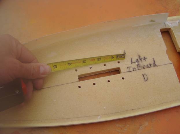
Measure for reinforcing blocks
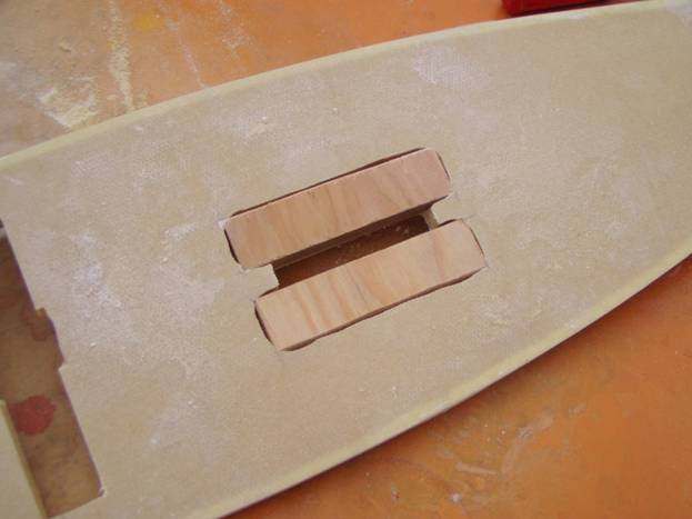
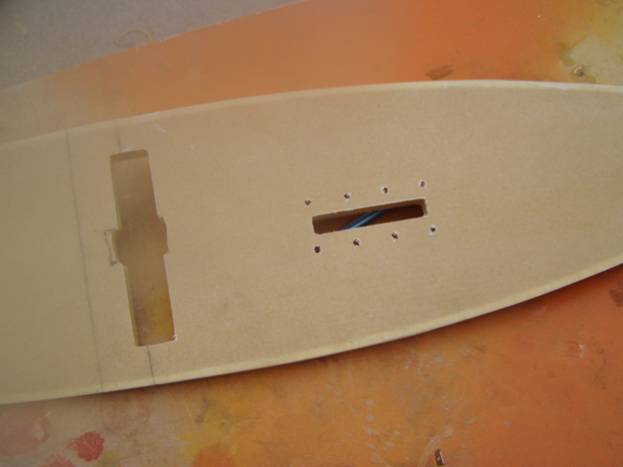
Rib Detail D
– this is the rib that mounts the main gear leg and will be handled on it own page and can be found here.
Rib E-
Need photo
Rib F-
- Rib G - Rib G – This is the outboard most rib and is bonded to the end of the outboard spar. It will require a flange along the top inboard edge. This flange will not need to cover the last 8.5” of the rib as this is aileron area, not wing skin area. Also mark the bottom inboard edge. This rib will need the level line marked on both sides as well as the location of the spar.