Chapter 7 - The Wing
Section 4 - Wing Internals
Fuel Tank Ports
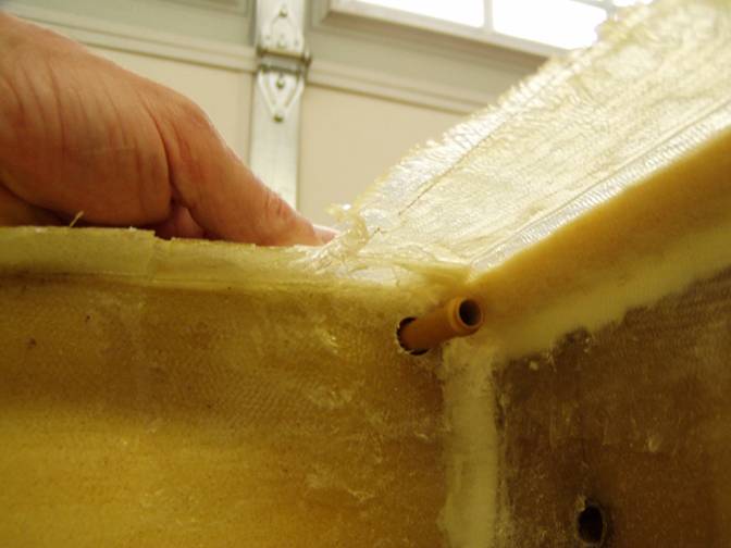
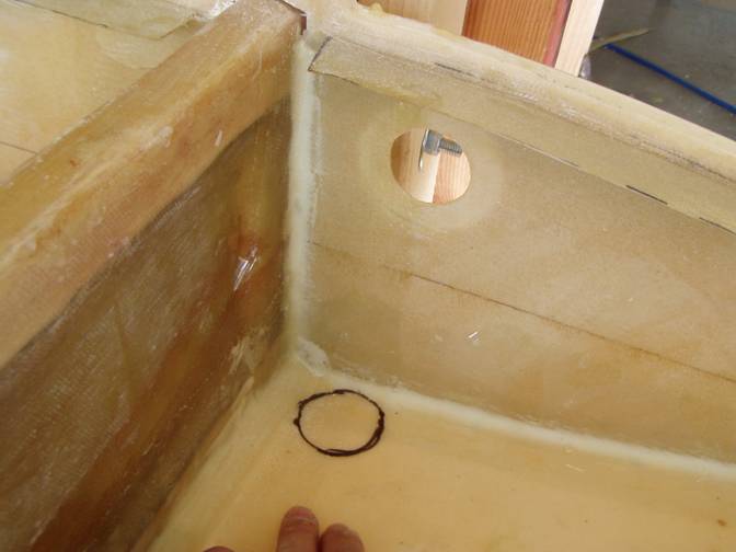
There are three fuel tank ports that have to bee installed: the fuel tank vent, the fuel tank outlet fitting and the fuel drain. Let us start with the fuel tank vent which is fabricated by either welding or bolting a AN848-6D fitting to an 1/8” aluminum plate as shown below. The weld/Nut attachment to the 1/8” plate does not have to be hermetic (fuel proof) as the seal is inside the tank, not at the plate. The position of the fitting is on the forward side of the spar, outboard side of the D rib, as high as practical. Look at the pictures that show the location of the fuel vent from the view of inside the outboard most fuel bay. The vent is located as high as possible.
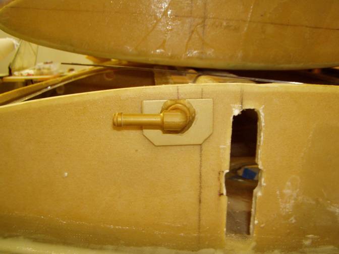
Location of fuel vent as seen from the outboard side of the D rib
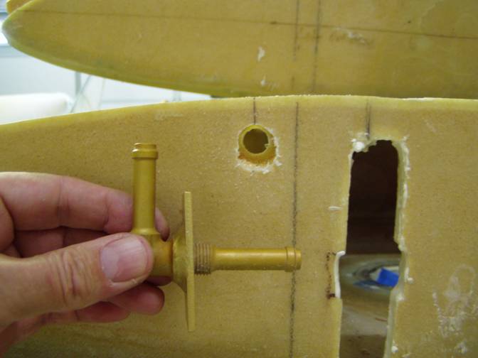
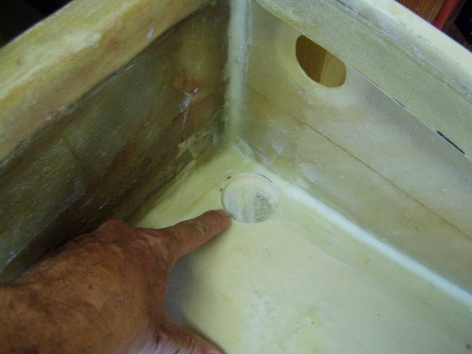
Once the position has been determined drill through the D rib, clearing the glass just enough to allow the fitting to mount flush with the outside of the rib.
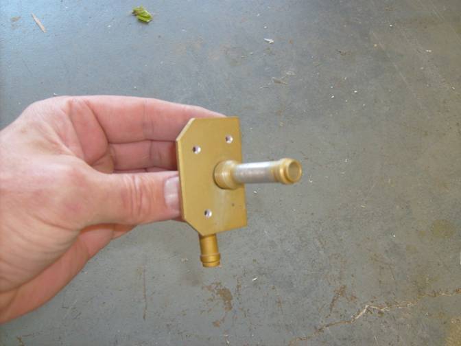
Fitting may be welded or bolted to the plate
First dig out the foam in the hole and replace with thick micro. Let this cure.
Use scotchbrite to polish the inboard vent tube to improve the ability of the epoxy flox mixture that will hold it, to bond.
Remove anodine with Scotchbrite – This is where the tank seal is made
Fuel Vent as high in the tank as possible
Location of the fuel vent
Once the micro in the hole has cured and the fitting has been test fit for the last time, rivet it into place with 1/8” pull type rivets through the outside glass skin of the D rib.
Finally, mix a thick epoxy and flox mixture with some cabosil and fill the entire space around the fitting and the mounting hole. Be sure not to get any in the vent fitting so as to plug it up. Let cure.
Next we will work on the two other fuel ports, the drain and the fuel outlet. Aluminum welding flanges are used to provide the NPT fitting thread into the tank.
Collect the following parts:
2 each AN867-3 Welding flanges for the fuel drains
2 each AN867-1 Alum Welding flanges for the fuel outlet
Parts Prep:
The smaller alum welding flanges with the 1/8” npt holes are used for the fuel drains. The outer raised ridge is ground down as shown in the following series of photos. Roughen the entire part with a grinder or rough sandpaper.
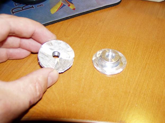
Raised lip on the smaller flanges is cut off
The larger aluminum welding flanges are used for the fuel outlet with at finger strainers installed. The fuel outlet flanges have one side cut down so we can mount these low in the tank. They are cut as the following photo shows and again the entire part is roughened up with the grinder.
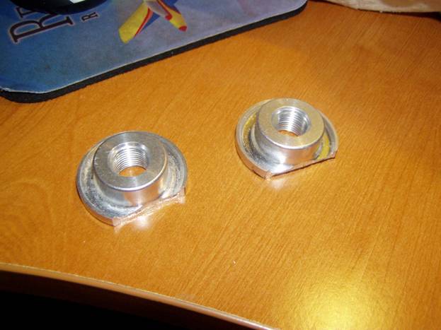
Fuel Strainer Welding Tabs Cut
Familiarize yourself with the fittings that screw into the aluminum flanges. We do not want to install one of the flanges inside out. The easiest way to remember as to which way the flanges go is to keep in mind that the knobby end of the flange points outside the tank. The fittings thread into this raised portion of the flange and the fittings must be installed from outside the tank. Practice installing the fittings so this is clear.
Use the large flange as a template and mark its location on the outside of the A rib, right under the fuel sender, with the flat side of the flange down and about ¼” above the bottom wing skin.
The fuel outlet will be placed over the fuel drain. The fuel drain will actually create a well at the bottom of the tank and the fuel drain will be placed about ¼” above the bottom of the tank. This will increase the amount of unuseable fuel in the tank, but will allow any water that collects to be below where we pick up the fuel.
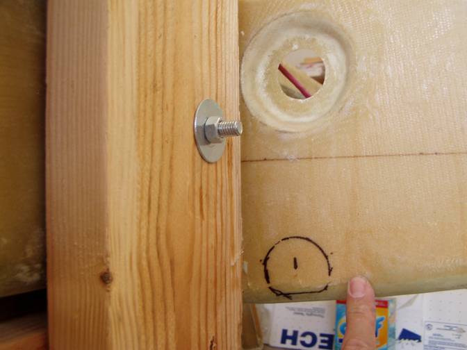
Proper location of the fuel pickup flange
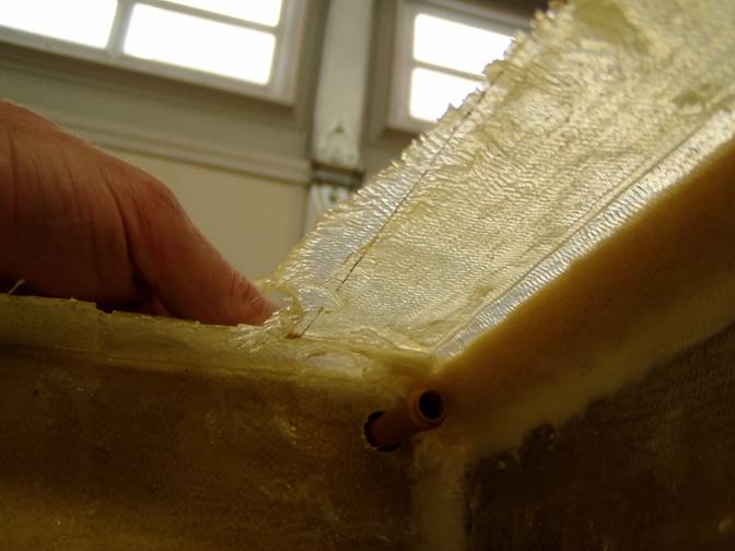
Trim the outer layer of glass from the outside of the A rib and remove the foam. See the following photo. The flat side of the flange is mounted in this pocket and it should rest flat against the inside fiberglass rib skin. Prep this pocket by removing some of the foam and fill with thick micro.
Location of the small flange
The smaller flange is located at the lowest point in the fuel bay which is the inboard side of the A-B fuel bay just in front of the spar and close to the A rib.
Mark this location and prep the pocket as you did the other one. The flat side of the flange will be mounted up, so make a hole in the bottom wing skin to allow the threaded portion of the flange to extend through the wing skin. Prep this pocket as you did the others.
Fuel drain pocket
Test fit the fittings and insure the drain is as low as possible and that the fuel pickup is not too low or too high, about ¼” off the bottom of the fuel floor. The threaded side of the flanges should point out side the tank. Cut the holes all the way through the fuel bay to allow the fittings to be threaded into place. Test fit the fittings to insure one last time you have them oriented properly.
To install the flanges, use an epoxy flox mixture. Fill the holes of the flanges with softened bees wax, this can be purchased at the hardware store and is used to lubricate drawer slides. Be careful not to get any wax on any other part of the flange. Complexly coat the pocket with the flox mixture, wet out the flange with the epoxy mixture and press it into place. Remove any excess, but the flange should be completely encapsulated in the epoxy mixture with the exception of the hole for the fitting. Use duct tape to hold it in place while the epoxy cures.
Complete.