Chapter 7 - The Wing
Section 4 - Wing Internals
Installing aileron control System
Once we have post cured the inside of the bays it is time to start installing the components in the wing. Give the bays a good cleaning and let’s get started.
To install the Aileron control system we will start with the aileron bellcrank. Refer to the following picture to get an idea of the general orientation of the bellcrank. This bellcrank is located in the slot in the D rib. Notice that the long arm is located inside the wing bay between the C and D ribs and points toward the spar. The brackets are inside the bay and the small arm extends through the notch in the D rib between the two wood hard points. The control linkage connecting aileron bellcrank and the aileron itself passes between the D and E ribs and out the aft spar.
Aileron Bellcrank
There should already be holes drilled through the D rib ready to accept the aileron bellcrank brackets. The holes may be a bit off so it may be necessary to match drill them to get the AN3 bolts to line up correctly. The bellcrank should be centered between the two hard points in the rib and the bellcrank should not interfere with anything throughout its full movement. This can not really be determined until the push/pull tube is installed because it limits the bellcranks range. Sight straight on at the outboard side of the D rib and look at the bellcrank bearing. It should be centered up and down with respect to the notch in the D rib.
At this point do not trim the front and rear of the slot as the travel of the bellcrank is limited by the idler bellcrank which will be installed next. We may need to trim the slot later, however
Drill the holes and use AN3- 10A bolts, An960-10 washers and AN364-1032A nuts to secure the bracket. The bolt head should be in the bay and the nut should be between the D and E ribs so they can be easily inspected with the wing tip removed. The AN3-10A is a nominal size and you may need a longer or shorter bolt; be sure there are at least two threads exposed beyond the nut, and too many may mean the threads are bottoming out in the nut.
Once we are happy with the position of the aileron bellcrank and it is firmly bolted in place we will move on to positioning the idler bellcrank.
Devise a way to clamp the idler bellcrank in position without using the mounting bolts. There is some alignment that has to be performed before we can finalize the location and drill the holes. I used a small wooden brace and a clamp as shown in the following photo.
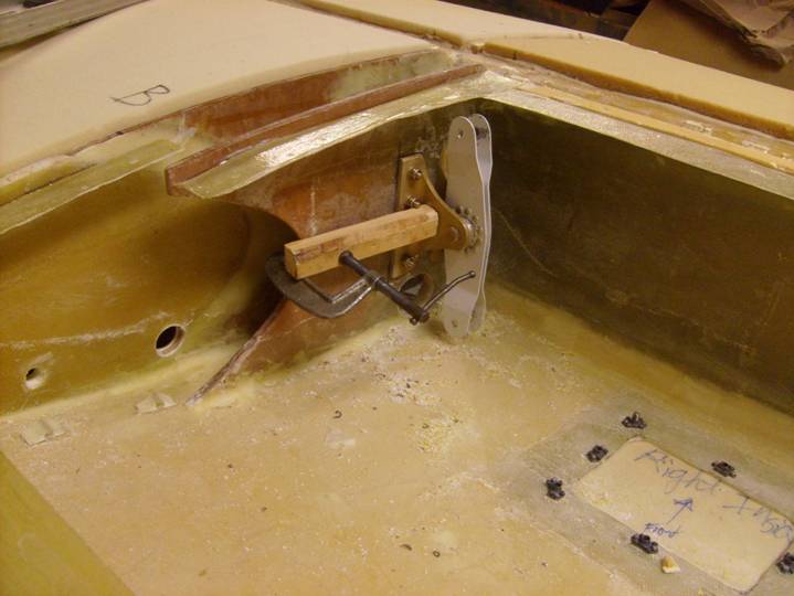
Clamping Scheme to temporarily hold the idler bellcrank in place
There are several conditions that must be met to define the position of the idler bellcrank. To locate it properly we must fabricate the control tube that connects the idler bellcrank to the aileron bellcrank. We will do this now.
Obtain a xxx length of xxx tubing, two xxx and two rod ends xxx. Examine the rod ends and the xxx in the following photos. Once the proper length of the aluminum tube is determined we will use steel pop rivets to attatch the tube to the xxx. First we need to approximate the length of the tube. Screw the rod end bearings all the way onto the xxx and then back them off three complete turns. Notice that the rod end bearings are screwed in further than we will want them when we are done. We want the bearing to be centered, but our first attempt at cutting the tube, we will err on the side of caution and make the tube a bit longer than necessary. Install the xxx into the full length of the aluminum tubing. Measure the distance from the center of one bearing centerline to the center of the other bearing center line. Write this length down. Now center the idler arm and the aileron bellcrank and measure the distance between the two control tube bolt centerlines. The idler is centered when it is perfectly vertical and the bellcrank is centered when the smaller arm is perfectly centered in the D rib slot. This can easily be judged by centering the smaller arm between the two center mounting screws in the bellcrank bracket. Now subtract the two numbers---this is the amount you want to cut off the aluminum tube. Do this and reinstall the tube end. Now you can install the push/pull tube between the idler and the bellcrank (the tube attatches to the top arm of the idler).
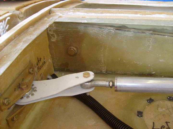
Push/Pull Tube installed on aileron Bellcrank
Notice that in the above photo the rod end bearing is threaded almost all the way onto the push tube end. This is the way it is done until we determine the exact length of the tube.
Now that the tube is installed we want to determine its proper length. Center the two bellcranks and adjust the rod ends so the aileron arm is centered when the idler is verticle.
Next we need to properly position the idler bracket, as mentioned above there are several conditions that must be met for its proper location to be determine. Take your second push/pull tube and assemble it like you did the first (dont' worry about the length at this point). Run this one inthrough the hole in the A rib and B ribs and attatch to the lower arm of the idler. Center this tube in the hole in the A rib. This tube will simulate the control tube running to the control stick.
The idler should be centered between the bottom skin and the top skin. Since the top skin is not in place, its position will have to be determined by referencing the flange on the top of the BB rib. Next the push/pull tube running to the control stick must clear both the B and BB ribs when the tube is moved through all possible positions in the hole in the A rib. Finally, the idler should be vertical with respect to the spar. That is, the top of the idler should be the same distance from the spar as the bottom arm.
It will be an iterative process to meet all of these conditions, but when they have all been met, match a couple of holes through the BB rib and install temporary hardware.
Next, the hole in the C rib needs to be enlarged to clear the push/pull tube throughout its range of movement. There should be at least ½” in all directions. Once the hole has been trimmed to clear the tube, the exposed foam can be trimmed and replaced with thick micro as we do with all exposed edges. See the following photos.
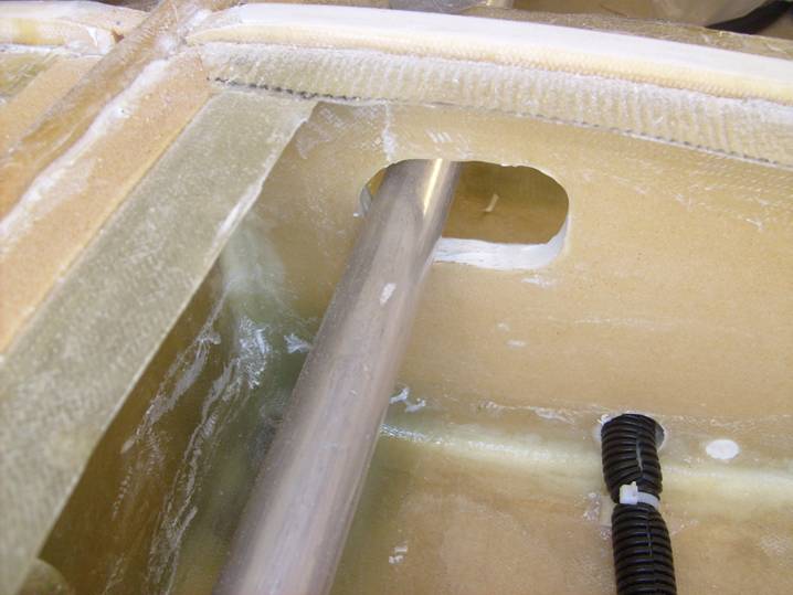
Tube Clears C rib
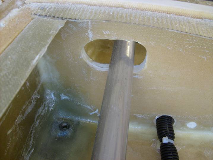
Tube Clears C rib
Once again insure that everything is centered and the tubes are clear from all ribs. Move the control tube that exits the A rib through all range of motion and insure neither tube comes close to any rib surface. Enlarge holes as needed.
When satisfied, drill all of the holes to mount the idler bellcrank and install AN3 hardware. The nuts should be installed in the B – C bay so they can be inspected through the acess panel.
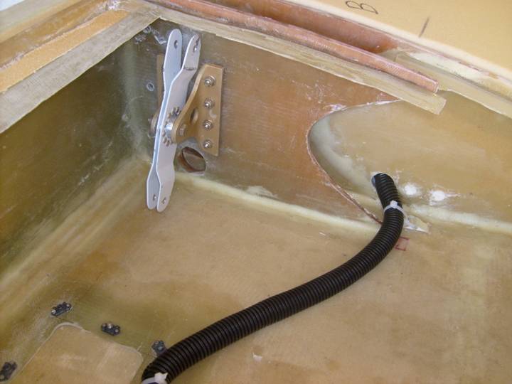
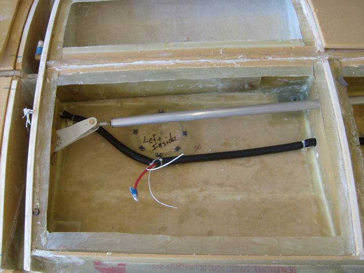
Idler Installed
Finally remove the aileron push/pull tube and accurately measure the exact distance between the two bolt holes in each rod end bearing. Record this as we want to maintain this. Look closely at the rod end bearing and notice there is a small hole that enables you to insure the bolt is suffeciently threaded. This defines one end of the bearings thread range. Now thread the rod end bearing all the way on, this defines the opposite end of the range. Center both rod end bearings between these two threaded positions. Now remeasure the distance between the two bolt holes in each rod end bearing. Compare this to the desired length. Cut the tube to return the complete assembly to the proper length. Drill eight 1/8” holes through the end of the tube and the tube ends and use steel cherry rivets to secure them. Finally mark the push/pull tube as to which side of the wing it belongs as the two side could be different length.
Good Job. The aileron system is complete.