Chapter 7 - The Wing
Section 4 - Wing Internals
Gear Legs and Tie Downs
Gear legs and tie downs
In this section we will accomplish two smaller details. The first will be to add a protective cap at the top of the gear leg mount. The gear leg will be installed and removed several times throughout the assembly process of the plane and we do not want to take a chance of driving the gear leg up and through the top skin by accident. We will install a small stop to prevent this.
Prepare two parts as shown int ehfollowing photo. A piece of pre-cured single layer BID laminate and a ¼” thick foam spacer.
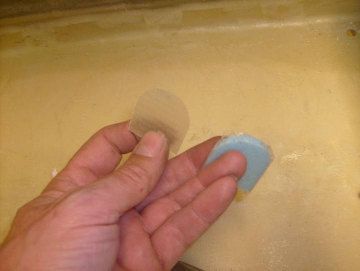
Gear Leg Stop
With the gear leg installed, trim the parts to fin atop the gear leg as shown in the following photo. Cover the foam spacer in packing tape. Position the parts atop the gear leg. Mix up a thick epoxy and flox mixture and create a good size radius of material between the single layer laminate, the spar and the two B ribs. Let Cure. The foam spacer can be removed or left in place.
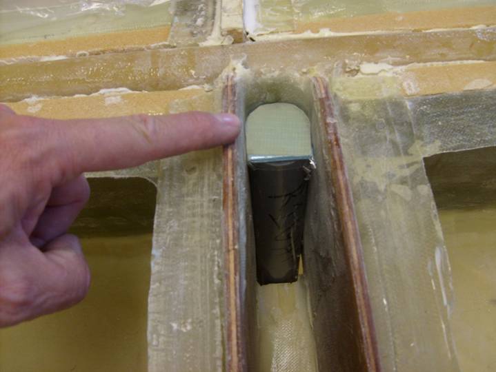
Position of Gear Leg Stop
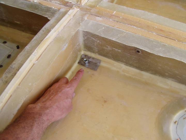
Next we will add a couple of tie down points in the wing. Remember the tie down point we added in the aft fuselage. You can refer back to that section to refresh your memory as to the techniques involved in this step. The tie down points are at the junction of the main spar and the C rib. It is placed on the aft side of the spar and the outboard side of the C rib. If you place it on the front side of the spar, your fuel will run out.
First cut two 2.5” X 1.25” rectangles of 1/16” mild steel as shown below. Place a bend in them so they conform with the foam triangle where the bottom wing skin meets the spar. See below.
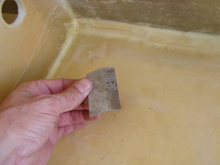
Mild Steel Plate with Bend
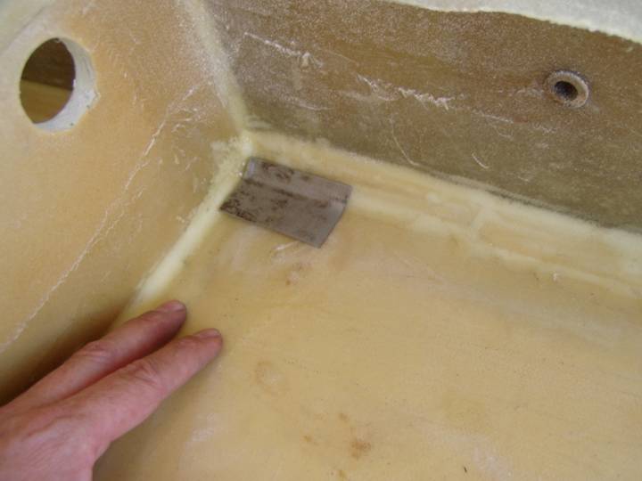
Proper position for Tie Down Point
Position a standard hardware store varity 3/8”-16 nut as shown below---1” from the inboard edge and centered front to back, but on the flat of the plate.
Placement of tie down Nut
Then drill a 3/8” hole in this location and weld the nut to the plate. Follow up your welding with a grinding to clean up the plate and chase the threads with a tap.
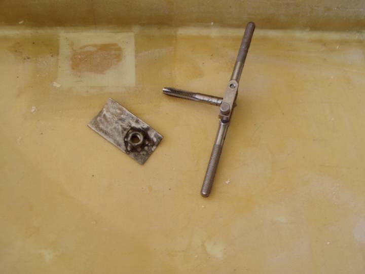
Welded Nut
Then drill a 3/8” hole in this location and weld the nut to the plate. Follow up your welding with a grinding to clean up the plate and chase the threads with a tap.
Prepare a paper template as shown in the following photo. We will use rectangles of BID with a single cut in them so that we a have a xxx square on the spar, xxxx on the rib, and xxx under our plate.
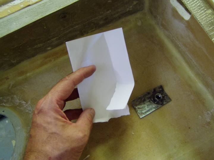
Paper template
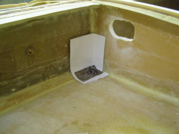
Position of Layup under plate
Create a six layer BID layup on a sheet of plastic, then transfer to the wing bay as shown below. It is best if each BID layer is slightly larger than the last so we have a beveled edge to our cured reinforcement. Let cure.
Cured Reinforcement
Position the plate and drill a slightly oversized hole through the wing bottom. Remove some foam from the wing skin and fill the hole with a thick micro. Let cure and then re-drill the hole.
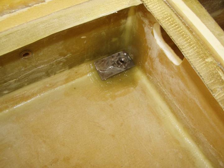
Obtain a 3/8”-16 eyebolt from the hardware store and wax the threads with mold release. Mix a thick flox and resin mixture and smear under the plate. Then seat the plate into position, thread the eyebolt up through the bottom and hang a 5 lb. weight or so from the eye bolt to hold the plate in position. Before the flox cures, add an additional 6 layers of BID to the top of the plate in the same manner as you did for the under plate laminates. Let cure. Remove the eye bolt and once again clean the threads with the tap.
Complete.