Chapter 7 - The Wing
Wing assembly
Once we have finished our main spars, ribs and aft spars, we are ready to begin the assembly of the wing. Before we do, let us review the major assembly stages. The spar is designed in three sections so we can built the wing in a standard 20 X 20 foot two car garage. We will mount the main spar right side up in a stand, mount the left outboard spar, and then assemble the left wing. The ribs will be bonded to the spar and then the leading and trailing edges. We will skin the wing bottom. The wing is then flipped over so we can sand and glass the bottom. The wing is righted and we will then repeat the process and build up the right wing. We then right the wing, remove both outboard wing sections and add all of the internal features—control tubes, fuel tank vent lines and the like—then skin the top, sand and glass.
Section 3 - Wing Assembly and Bottom Skin
Assembing Wing Frame - Ribs to Spar
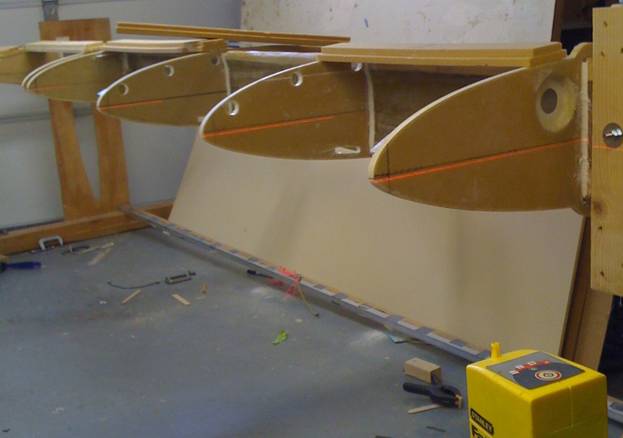
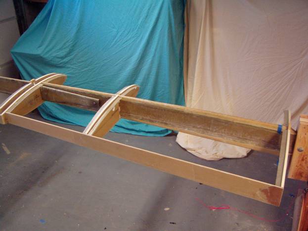
A simple wooden support is used to simulate the fuselage mounting arrangement and then this mount is stabilized on a stand. We want the spar to hang in its normal orientation without any induced stress. The photos below show the spar frame which is constructed from 2X6s and a couple of 3/8” bolts. The stands are made from 4X4s or doubled up 2X4s. Use plywood triangles to insure the support stand is very rigid. We do not want the spar to move at all once we have positioned it for assembly.
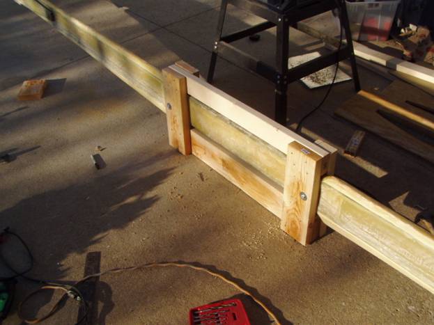
Spar Support Frame
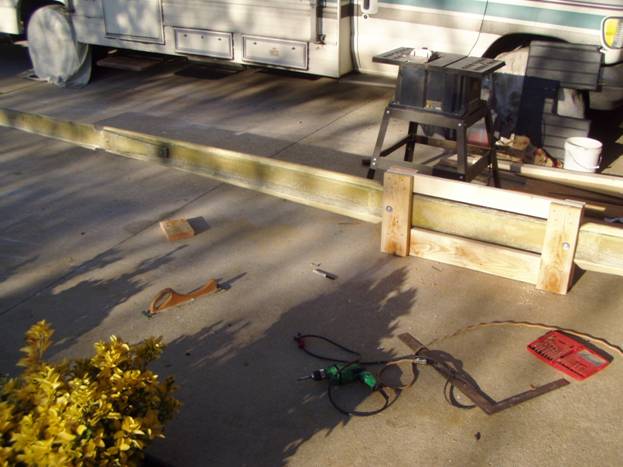
Spar Support Frame
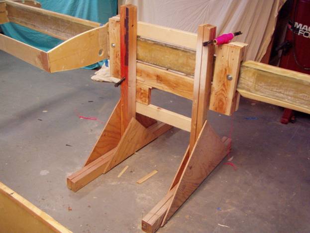
Spar Stand
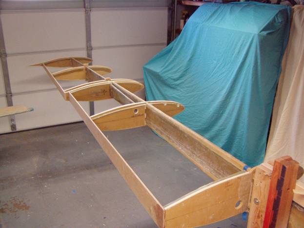
The spar needs to be leveled in three all axis. Use the horizontal and vertical level lines you marked on the spar earlier. To level the spar in the ‘pitch’ axis, find a flat spot on the front of the spar that can be used as a standardized reference point. Lay your level on this spot and mark it so it can be used throughout the wing assembly step. Once you are happy with the stability of your spar, we can begin test fitting out ribs into position. We assume the ribs have been prepared and are ready to go. The ribs should have level lines marked on both sides and a vertical line should be drawn on the front of the rib exactly one inch back from the very forward most tip. The spar should have the rib positions marked on both sides. There should be two lines drawn showing where the ribs intersect the spar. The ribs are vertical when the spar is in its normal orientation. When we slide the ribs into position, these lines will tell us where to orient them.
Test Fitting the Ribs –Characterizing the Spar
Let us get started. At this point the main spar should be mounted and stable. The outboard spar should be off, but you should be skilled at installing and removing it as we will do this a few times before we start bonding the ribs into place. Just use inexpensive hardware store 3/8” bolts for the time being. Later we will use aircraft grade hardware. The A rib should be trimmed so it will slide all the way down the spar and rest in its proper position. Use the vertical reference lines we marked earlier on the spar that show us where the rib is located. Then the C rib is trimmed in a like manner and slid onto the spar to its proper position. The D rib can be trimmed so the inboard end of the outboard spar can slip through the spar mounting hole. There may be interference with the bushings. The D rib is set aside for a bit.
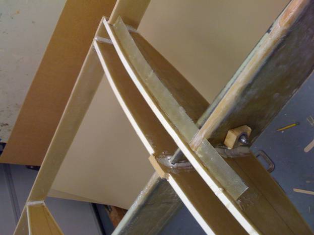
With the A and C ribs slid onto the main spar, bolt on the outboard spar. The outboard spar should be clamped to the main spar with absolutely no play in any direction. Now trim and slid into position the E rib and the F rib. It is now time to characterize the outboard spar mounting.
Using a carpenter square
Using a carpenter's square and a couple of clamps, clamp the G rib to the end of the outboard spar. Now we can use our laser level with a horizontal laser line to align the level line marked on all of the ribs.
Position the A Rib
Position the laser level so it illuminates the level line marked on the in board side of all of the ribs. You will have to adjust the spar wing tip up and down to get the level lines to align in a level plane. The first job is to insure that the spar will be enclosed within the volume of the wing skin as defined by the A and G rib. If not, we will have to tweak the position of these ribs up or down to insure this condition. If the outboard spar sags a little at the joint we will have to bias the ribs upward to insure the spar is enclosed in the wing skins. Likewise if the outboard spar has a bit of a upward cant, we will have to bias the A and G rib downward to compensate. Once the position of the A and G rib has been determined the other ribs (C, E and F) can be adjusted or trimmed up and down so that all of the level lines drawn on the ribs align. Once you are satisfied with the vertical alignment of the ribs up and down and are happy that the spar is lower than the top and bottom wing skins, mark the position of the rib's level line on the spar. Use a fine tip sharpie marker to draw a line where the laser level paints its line on the spar where the rib’s level line intersects. We will refer to this at the level line on the spar.
Now it is time to align the ribs front to back. Set the laser level up with a vertical laser beam. Place it so it paints a vertical line on all of the lines that were drawn on the ribs one inch back from the front tip of the ribs. The first thing to notice is whether there is a forward or rearward (with respect to the aircraft) bias of the outboard spar. One of my spars was biased to the front a bit and I had to install a washer between the mounting bolt on the outboard side between the outboard spar and the main spar to compensate. Once any gross adjustments are made like this, the ribs are trimmed so that all of the vertical reference lines (again, these are the vertical lines that were drawn an inch back from the front tips of all of the ribs) are in alignment. We have now completed the preliminary alignment of the ribs. We are ready to begin bonding them.
Understanding the Process to Position the Ribs
This is a good place to again describe the procedure used to properly position each rib. There are multiple degrees of freedom for the ribs. They must be level as defined by the level line running front to back. To insure that this case is met we will simply orient the level line marked on the ribs to the level line we marked on the spar in the above step and then insure the rib level lines are in fact level. They must be not be twisted and must be in the proper position along the spar. Here we will use the rib position lines we drew on the spar earlier. They must be square to the spar—we use a carpenters square to hold the rib in place while our 5 minute epoxy cures so this condition is met. The leading edge tip must be the correct distance from the spar reference plane. This is satisfied by using our laser level with a vertical oriented beam to align the vertical lines on the front of the ribs.
Bond the Ribs into Place
We are now ready to bond the ribs into place. We will use small mixtures of 5 minute epoxy and cotton flox to tack the ribs into place one at a time. Start with the A rib and the F rib. Use the laser level to insure the ribs are level and a carpenter’s square to insure the ribs are square to the spar.
Rib Position Lines marked on Spar
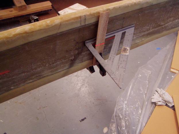
Carpenter's Square mounted to Spar
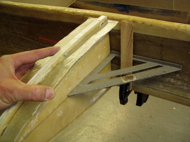
Square the ribs to the Spar
Bond the C rib and F rib into place. Make a 5 min epoxy and flox radius on both sides of the rib. You only need enough to hold the rib in proper position as we will later use micro to create a full radius. Now the D rib and E rib can be bonded into place. Insure that the D rib is bonded to the main spar and the E rib is bonded to the outboard spar and that the outboard spar is not bonded to the main spar (the E rib is just a tad smaller than the D rib, don't mix them up).
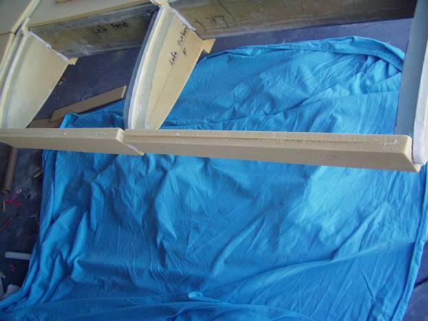
There is a 2 inch space between the D and E ribs
The D and E ribs should be uniformly spaced 2” apart. Bond on the front B rib, the section in front of the spar. Finally, bond the G wing tip rib. At this point we will need to support the wing structure at the G rib because the weight behind the spar is greater than in front of the spar and the wing will begin to twist. Use a simple stand clamped to the G rib to insure it’s level line is in fact level. Once the ribs are tacked into place the leading edges and trailing edges can be bonded on as well. Again use the 5 min epoxy and flox to tack them into place.
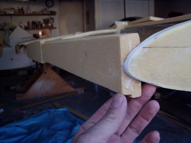
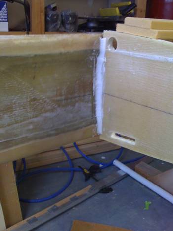
The rear inboard spar
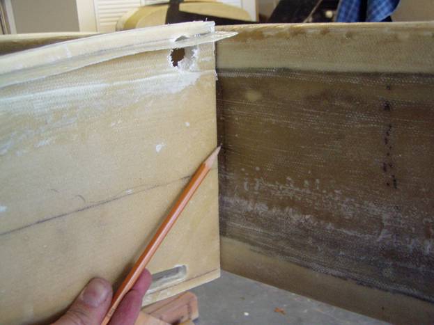
The rear inboard spar rests on the back of the A rib and C rib, but butts up against the side of the D rib. Do not attempt to attach the rear inboard spar to the back of the D rib or there will be a big bow in it. You can draw a line on the inboard side of the D rib 1 3/8" forward of the back edge. This will be the back side of the rear inboard spar.
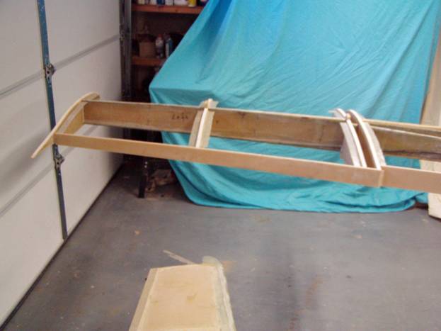
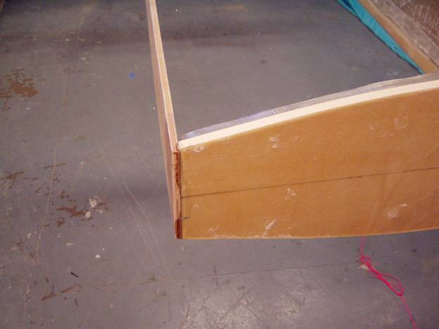
The Rear Outboard spar
The rear outboard spar is bonded to Ribs E, F and G ribs. Do not bond the rear outboard spar to rib D. Note that the outboard spar mounts to the outboard side of the D rib and to the back of the E rib. Therefore the D rib is about 3/4" longer than the E rib. Draw a vertical line on the inboard side of the G rib 8 inches forward from the very back of the rib. The back of the rear inboard spar will rest against this line.
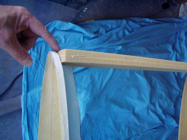
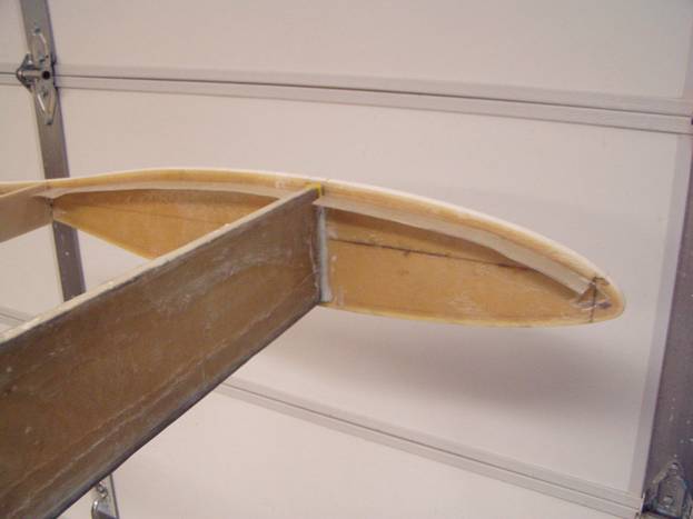
The leading edges in place
The leading edges are made from 2 each 3” wide strips of ½” thick last-a-foam bonded together with micro. When tacking the leading edges in place, insure that the correct spacing between the ribs is maintained. It is easy to spread the ribs without noticing. Insure that the leading edges are just proud of the front of the ribs and that the frond edge is vertical.
Once the leading edges and trailing edges are tacked into position we can now do one last inspection of the wing assy. Repeat all of your alignment measurements. It is easy to reposition a rib at this stage in the game. It is only held together with dabs of 5 minute epoxy and flox.
Once satisfied with your wing frame, use a thick micro to ceate radius at all of the joints between the ribs, spars, leading and trailing edges . Then add a two layer BID strip over each joint extending two inches onto each side of the joint. Let cure. Trim to the edge of the ribs and spars.
We can now start working on our main gear mounting attach points.