Chapter 8 - Mounting the Wing to the Fuselage
Section 1 - Wing to Fuselage
Wing attach to fuselage
The lion share of the wing construction is behind us and we are ready to mate the wing and fuselage. This is a major milestone as we are joining the two major components.
The wing spar passes through the fuselage under the pilots kness and is enclosed in a wing spar tunnel. Two bolts secure the wing spar to the fuselage passing the wing loads to the fuselage.
Just behind the seat, the wing trailing edge attaches to brackets transferring wing torsion loads to the fuselage.
First we will build wing spar support plates that will carry the bushing similar to the ones in the wing spar. The major wing attach bolts will be supported by these. Second a slot is cut into the bottom of the fuselage to accept the spar. The wing is leveled and the fuselage is lowered onto the wing spar. The phenolic plates are bolted into place, then bonded to the fuselage; the wing spar bolts and wing are removed with the phenolic plates remaining in place. We add some fiberglass to permanently fix the plates to the fuselage. We build a spar tunnel, a reinforced three sided box built onto and around the center section of the wing spar.
Next we reinstall the wing, and affix the rear spar attach brackets to the fuselage.
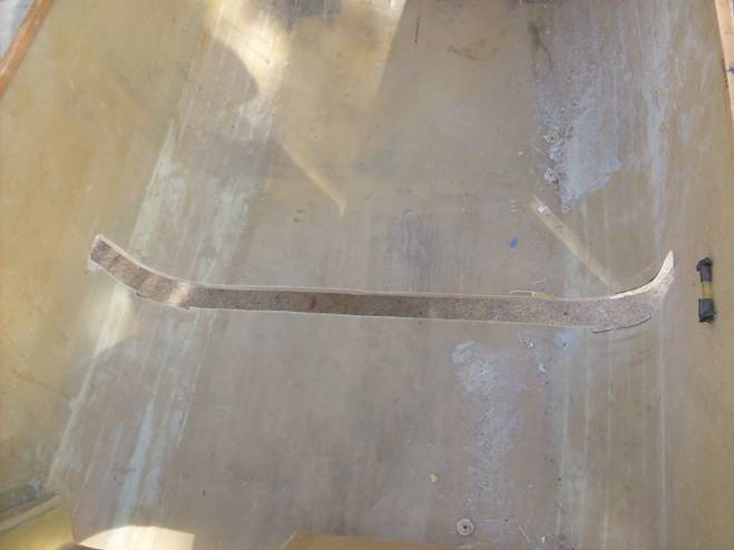
Lets get started. The wing is glassed and probably still mounted to the center wing stand. The center stand is removed and replaced by a pair of special saw horses. Do not rest the wing wiily nilly on a set of supports. The weight of the wing could deform and damage our bottom wing skin if not properly positioned. The best way to support the wing now is by fabricating a pair of supports that run span wise at the C rib that have the mating shape of the bottom wing. Cover these with several layers of foam. Never support the wing between the ribs. These shaped supports can be strapped to the wing and then mate to the saw horses. These saw horses will be used to support the wing when we fabricate the wing control surfaces and when we prep and paint the wing. Later we will want to lower the wing to near ground level, and we will build a special three legged support for this purpose.
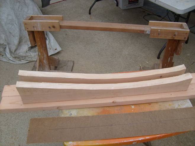
Supports cut to the shape of the lower wing
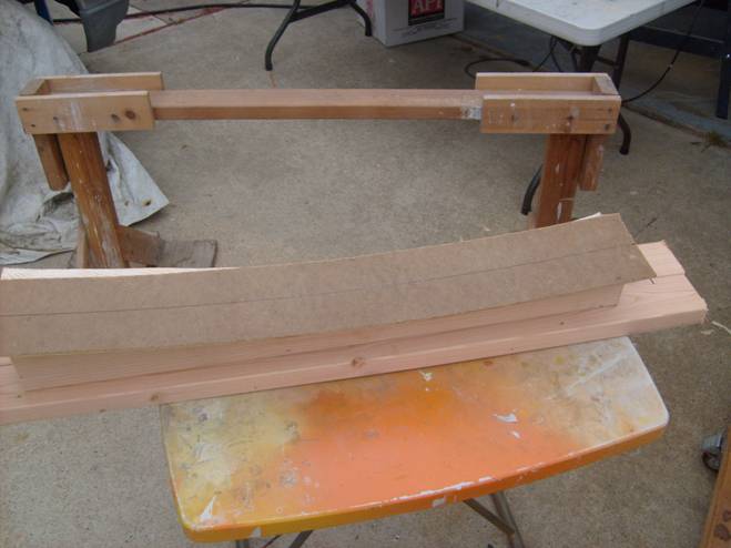
Wide strip of mason will distribute the weight of the wing over a larger area of wing skin
Support the wing on the saw horse stands positioned at the C ribs and remove the center stand, exposing the center section of the spar.
If the spar attach bushings and crush plates have not been installed already, do this now. Fabricate a set of bushings for the wing support plates as well. Drill the holes through the wings spar undersized and then ream to .75”. A .75 unibit works well for this operation. Bond in the center bushings with structural adhesive centered on the spar.
Set of wing attach bushings
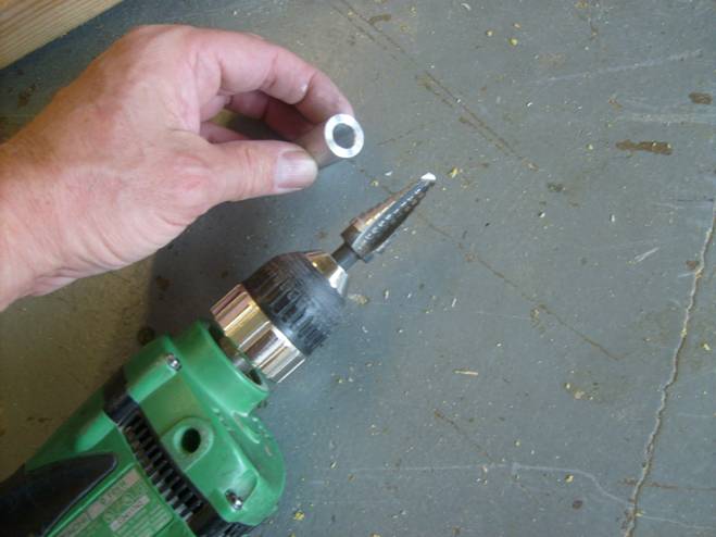
3/4" Unibit to drill through crush plates to match outside of bushing
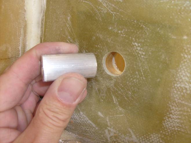
Test Fit bushing in Wing Spar
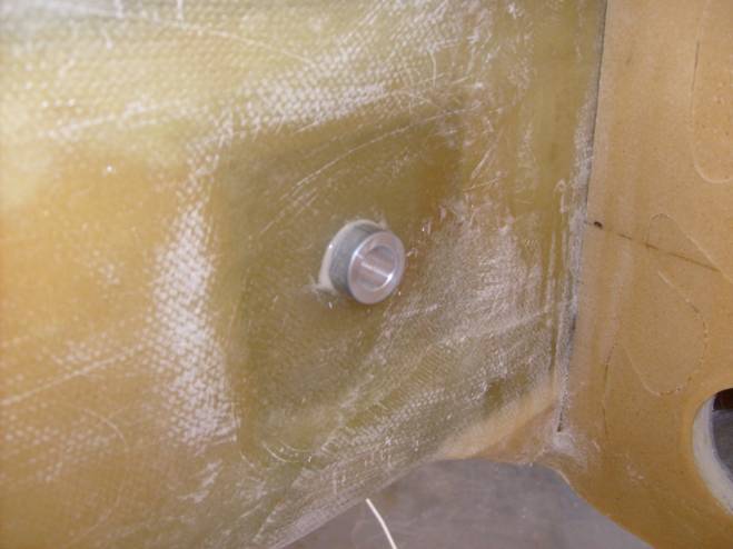
Bushing bonded into Place
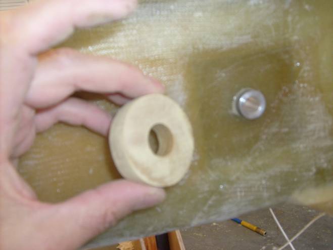
Fabricate ½” thick phenolic crush plates. These look like doughnuts, are xxx” in diameter and have the matching .75” hole drilled with the unibit. These slide over the exposed spar attach bushings and are attached to the spar with an epoxy flox mixture.
Crush Plates
Rounded top on Crush Plate to ease wing installation
Rough up Back side to be bonded to spar
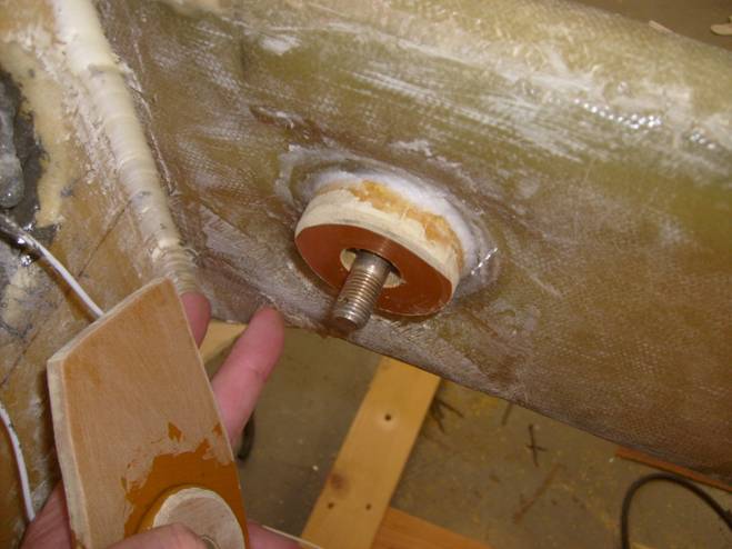
Installed Spar Crush Plate
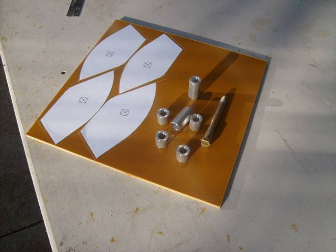
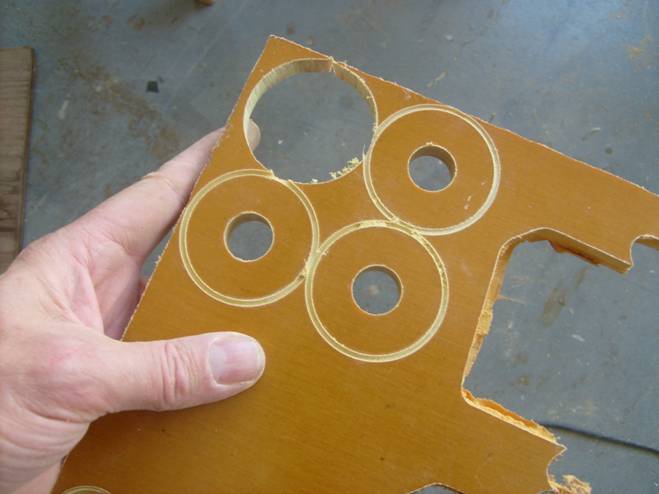
Next fabricate the wing spar support plates from ¼” phenolic,. Use the 1:1 drawings as a guide. The center hole is drilled using he ¾” unitbit on a drill press. Label these as to Left Right, front and aft. Each will be unique. Fabricate 4 crush plates the same dimension as the ones mounted on the wing spar, except out of ¼” phenolic.
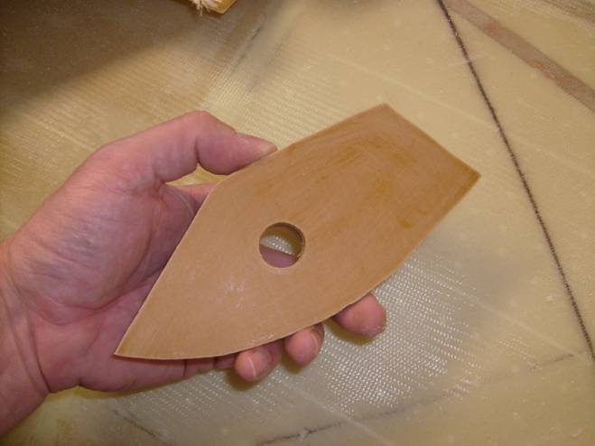
Support Plate
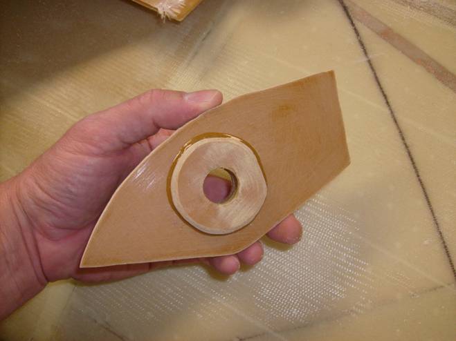
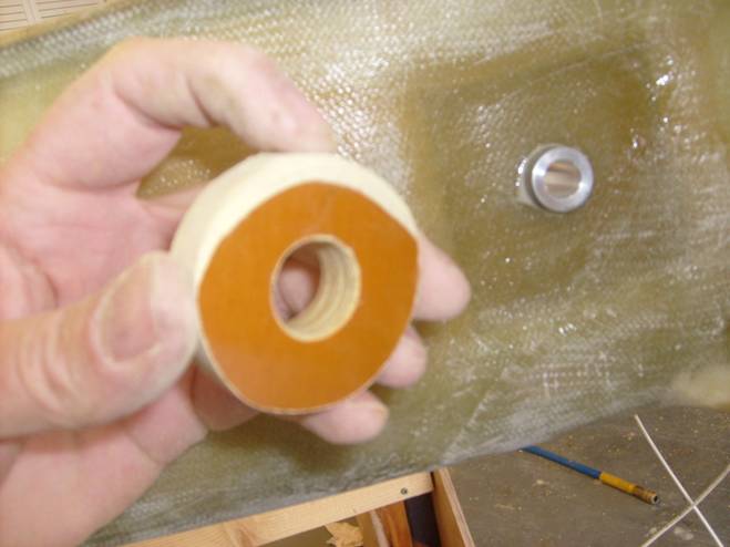
Support Plate with Crush Plate bonded in Place
Test Fit Support Plates on Spar
Bond these crush plates to the phenolic wing spar support plates using the four shorter bushings as alignment guides. 20 minute epoxy is fine for this. Use hardware store bolts to attach the phenolic plates to the wing spar. The curved side goes to the outside to match the curve of the inside of the fuselage and the inboard edge will be vertical. Properly orient the plates. These plates need to be mounted flat so that the two crush plates, the ones on the spar and the ones on the phenolic spar support plates are absolutely flush. If this is not the care, do not panic. Press out the bushing in the phenolic support plate, use the unibit to widen the bushing hole slightly so the bushing can wobble enough to allow the crush plates to be flush when bolted together. Once this is achieved, use structural adhesive to bond the bushing into the spar support plate while clamped into place against the spar. Be sure to insure the inboard edge of the support plate is vertical to the spar. The bushings in the phenolic plates need to be flush (or slightly inset) with the outside surface. Bolt clamping pressure can not be applied to the bushing, only the phenolic crush plate. Once we have completed the phenolic spar support plates it is time to test fit the wing and fuselage.
Grease the inside of the bushings with white lithium grease.
Fabricate a wing saddle.
The wing needs to be supported in three places in the saddle and the saddle needs to stand on three adjustable feet. The wing needs to be supported as it will in the aircraft. Any support (out at the wing tips for example) can twist the wing out of its natural alignment.
Next decide where you are going to join the wing and fuselage; I used my 2 car garage. Alignment marks need to be precisely laid out. Figure out how and where you want to position your aircraft for the fitting operation. I had to orient my plane with one wing tip sticking out of the garage door and the whole airplane turned about 10 degrees so the vertical stabilizer didn’t hit the wall of the garage.
Before we go any further, reevaluate the square-ness and dimensionality of the wing and fuselage. It is possible that during post curing or some for other reason, the fuse or wing is not as true as you remember it being.
Re-measure the wing span to insure it is evenly divided between the two wing halves. You should have a vertical line drawn on the center of the front side of your spar to mark the center, and on the outside of the G ribs that mark the location of the spar. The forward line drawsnon the outside of the G rib represents the location of the back of the main spar (but the front of the outboard spar).
Level the wing on the ground in its wing saddle. Are the level lines on the A and G ribs still level with respect to each other?
Level the fuselage and remember the best places to place a carpenter’s level to insure it is level in both axis.
Once you are happy with the trueness of the wing and fuselage, it is time to layout the alignment marks on the floor. My garage floor is coated with epoxy paint so I made my alignment marks with a sharpie pen right on to the floor. It cleans up later easily with acetone. Start with the wing position as it is the most unwieldy. Once positioned, use a plumb bob to mark the position on the floor of the front of the outboard spar as marked on both of the G ribs. (this is the same as the back side of the main spar). Move the wing and use a laser level to paint a line connecting the two points defining the full span of the rear of the main wing spar. Mark a line on the ground 6” or so on each side of the plumb bob mark at each wing tip, and in the middle of the spar. Measure ½ between the two wing tip marks and place a mark at the center of the spar. Reposition the wing and insure the middle mark lines up with the center of the spar and is equidistant from the two A ribs.
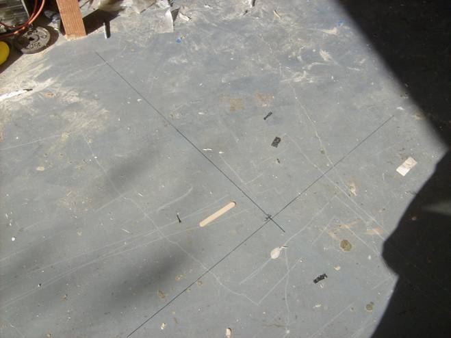
Wing and front Fuselage marking lines
The fuselage is going to be positioned 90 degrees to this line (of course) and we will use a plumb bob off the back of the vertical stab and off the vertical line drawn on the firewall to properly position the fuselage.
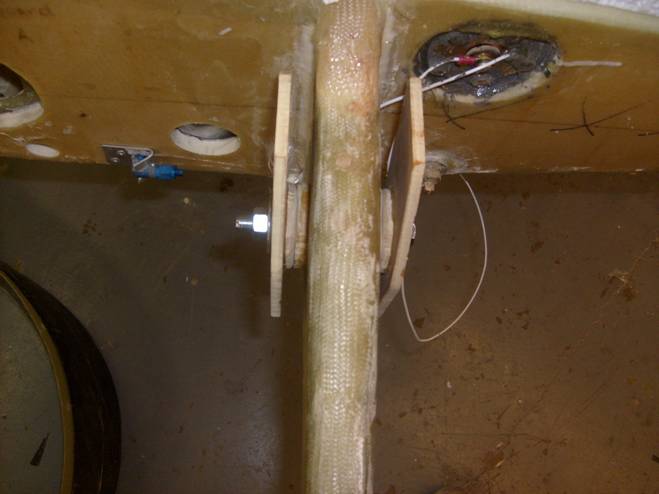
Before we can mate the fuselage to the wing we need to cut a notch in the bottom of the fuselage to allow the spar to nestle into place. The aft face of the main spar is located 34” behind the firewall. We will cut a 2” notch in the fuselage, one edge 34 ¼” and the other edge 32 1/4” back from the fire wall. The easiest way to mark this is to measure along the outsides of the fuselage and along the bottom of the fuselage from the edge of the firewall and match the two lines around the curved bottom corner. Since the sides flare out and the bottom flares down, the distance along the fuselage side is a bit longer than straight back from the firewall (but only about 1/8”). The top of the slot is located xxxx from the top of the longeron. Draw a line xxx inches down from the longeron roughly where the spar will go. Then measure back along the inside of the fuselage 32 3/8” and 34 3/8” making marks on this horizontal line. Then use a large T square and draw two lines perpendicular to the top longerons from these marks on the horizontal line down the side of the fuselage to the curved section. Flip the fuselage over and place marks on the flat bottom 32 3/8” and 34 3/8” back from the firewall, then connect these and extend them around the curved corner section. Use a 1” hole saw and make the corners at the top edges of the cut radius, then using a saber saw or cut off wheel, remove the section of fuselage to expose our spar slot. The slot may have to be widened a bit at the corners to allow the phenolic crush plates on the spar to pass through the slot.
Inside View of Wing Slot
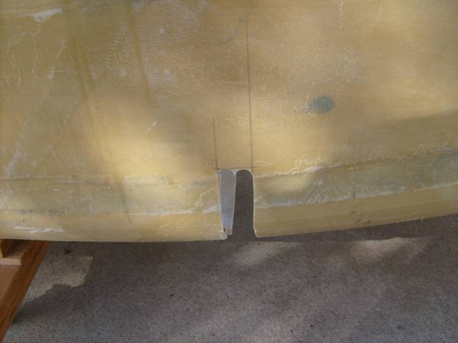
Outside View of Wing Slot
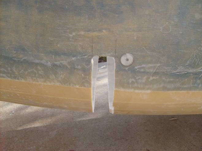
Closeup view of Wing Slot
Congratulations, we are ready to test fit the wing and fusleage.