Chapter 2 - Fabricating the Tail
Section 2 - Glassing the Vertical Stabilizer
Once the antenna is installed and the foam is smoothed to match the shape defined by the ribs, it is time to skin the vertical stabilizer. The first task is to create a ‘C’ channel on the trailing edge spar that will enclose the hinges. Scuff up the fiberglass of the rear spar. Then melt a wax crayola into the hinge mounting holes—this will protect the thread against getting gummed up with resin.
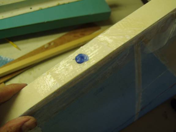
Fill the hinge holes with Wax
A flange needs to be created on the trailing edge spar 1 1/8” behind the trailing edge. Take strips of ply wood or other material and conver one side with packing tape. Clamp these on both sides to create the mold for the ‘C’ channel.
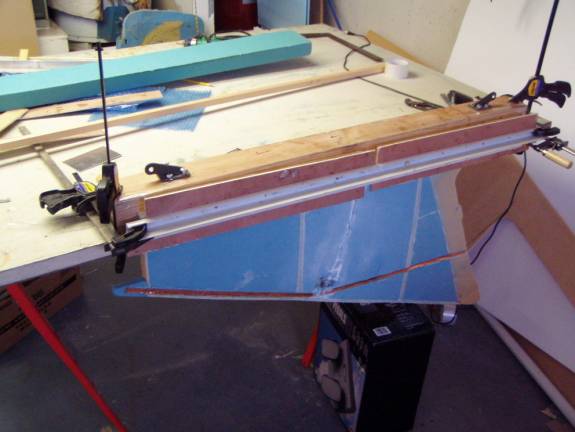
Straight Edges used to secure the ‘C’ channel mold
Here I used a 4X4 clamped to the work table to form the mold for one side of the ‘C’ channel and strips of plywood held in place with an aluminum angle and clamps. The inside of the 4X4 and the plywood are covered in packing tape to act as a mold release surface.
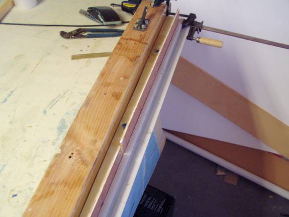
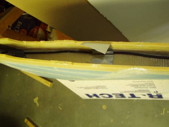
‘C’ Channel
formed by 4X4 and plywood Strips
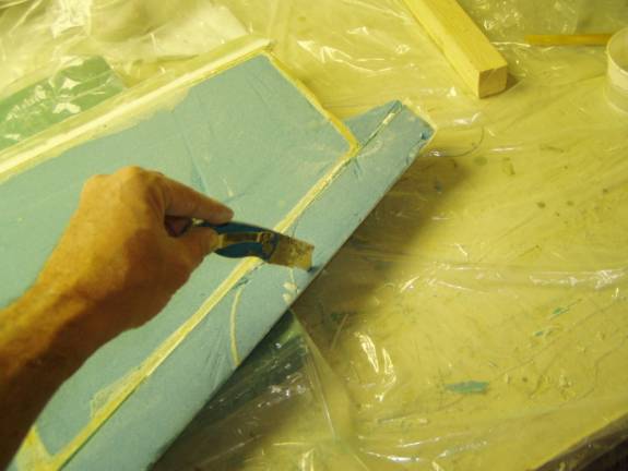
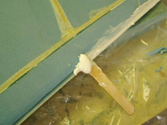
This is a close up view of the final ‘C’Channel. Prepare a mixture of thick micro and smooth it into the two corners of the channel. Then cut two strips of BID that will be laid into the slot to form our flanges.
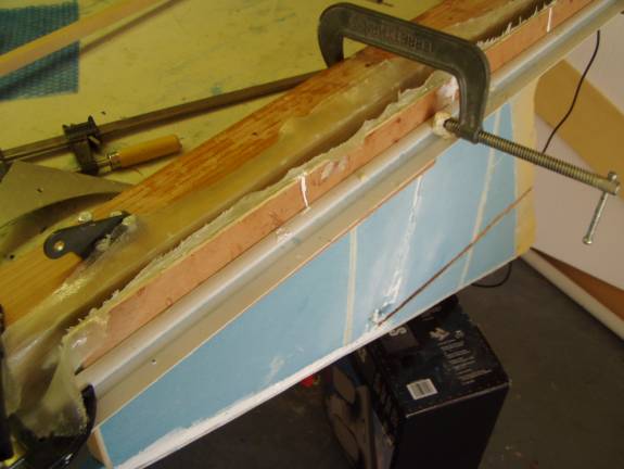
2 layer BID curing to form rear ‘C’ Channel
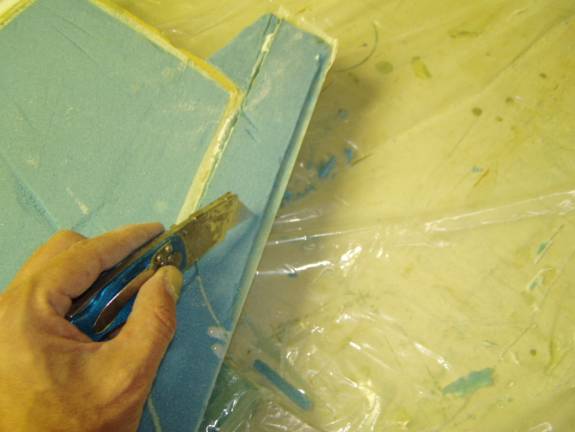
Lay up the two layers of BID on the 45 degree bias to form our flanges. When the flanges have cured, remove it from our fixture and trim the flanges to a length of 1 1/8” from the back of the vertical spar. Drill out the hinge holes and remove the wax.
5 Minute Epoxy holding coax cable in place
The antenna cable is routed from the rear of the bottom vertical spar, along the corner of the vertical side and the bottom spar, to the front of ther vertical fin. 5 minute epoxy is used to hold the cable in place while a thick micro is used to secure it in position, and then a single layer of BID is placed to hold it permenanelty in position.
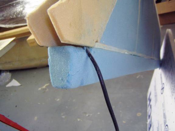
Exit point for the coax cable at the front of the vertical fin.
Final Preperation before skinning.
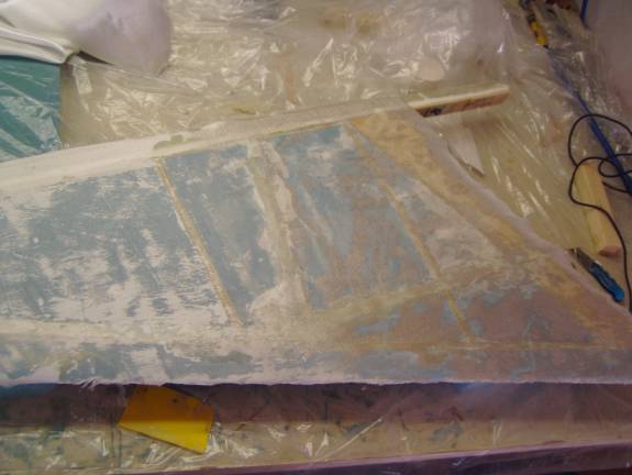
Give the vertical Fin a once over before skinning the out side. Rough up the out side edge of the rear spar flange with 40 grit sand paper. Fill all holes and imperfections. Here I used a combination of 2 part urethane foam to cover the foil tape of the antenna and micro past to fill smaller imperfections. Sand to the contour dictated by the ribs and finally vacuum the entire surface.
Surface Vacuumed and ready for Glass
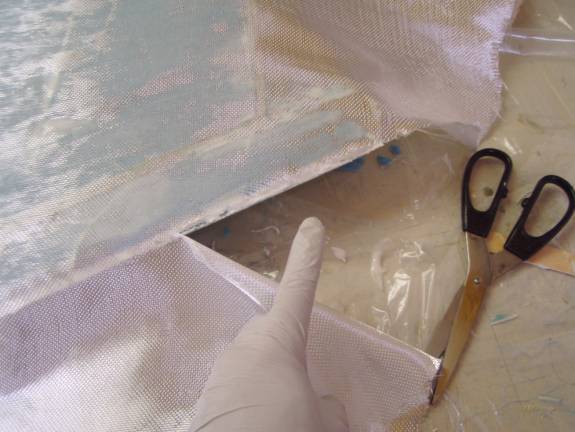
Cut a piece of UNI with the major glass fibers oriented in the same direction as the rear spar, a piece of BID on the 45 degree bias with respect to the rear spar and a piece of peel ply.
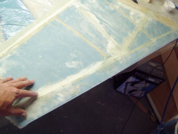
One layer of UNI smoothed into place
Slurry the foam surface and smooth out the UNI. Fully wet it out, then add the BID. The best way to obtain a light weight part with a good surface is to use the paper towel blot/ peel ply technique. After the final layer of BID is applied and fully wet out, place a layer of absorbent paper towels on the surface. Carefully smooth them out to soak up as much resin as resides on the surface. Do not press to hard on any single point as you can evacuate an area of resin. We are only looking to remove ‘excess’ resin. Once a dull surface, but not dry surface is obtained, place the peel ply and smooth it into position with a squeegee, the palm of the hand or the bristles of a brush. Again do not apply point pressure, as with the finger tips, this will create areas void of resin. The combination of the paper towels and the peel ply with remove as much resin as is practical, and provide a smooth finished surface.
After Cure
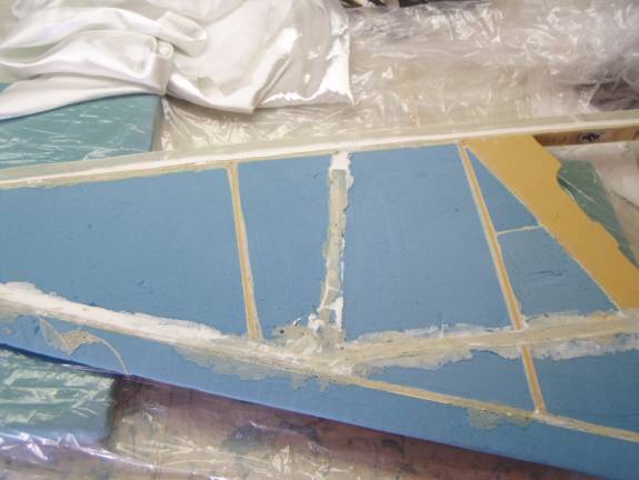
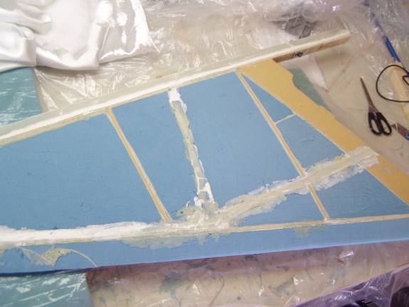
The above photo shows the skinned vertical fin. Many of the filled areas are seen through the glass, but it is smooth and flat. Carefully trim the leading edge right to the foam, sand straight with a straight edge covered in sand paper.
Prep the leading edge
Flip the vertical fin over and prepare to skin the second side. Trim back about a quarter of an inch of the foam from the leading edge being very careful not to disturbe or cut through the fiberglass skin on the other side.
Leading Edge reinforcement
This leading edge reinforcemtn only needs to run down to the point where the fins leading edge thickens. This is where the dorsal fin is attached latter.
Micro applied to Leading Edge
Take a small piece of sandpaper and radius the foam
at the leading edge slot. This will allow the fiberglass to lay smooth
into the slot. Vacuum
the entire vertical fin surface. Mix up a batch of thick micro and fill
the slot made in the leading edge. Then use the remaining micro
to fill imperfections in the skin, the small gaps between the leading
edge spar and the leading edge foam in the picture above need to be
filled, for example.
Trimming UNI to roll into Leading Edge Slot
Skin the second side as you did the fir with a layer of UNI, layer of BID and finally a layer of Peel ply. The only differencewith the second side is the manner that the glass is handled at the leading edge. It is trimmed very close to the leading edge and then pushed down into the micro paste as shown in this photo and the following one.,
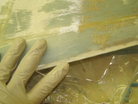
Close up of fiberglass smoothed into Micro on leading Edge
Slurry the foam surface and smooth out the UNI. Fully wet it out, then add the BID. Use paper towels and Peel Ply as described earlier to give a smooth light weight finish. Let cure.