Chapter 12- Fabricating the Tail
Section 2 - Vertical Stabilizer
Vertical Stab Foam and Antenna Installation
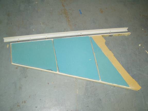
Cut Blocks to fill in between the Ribs
Cut sections of blue 2 lb. Polyurethane foam to fit the open spaces in the vertical fin. It is OK if you have to use multiple blocks to fill each open space.
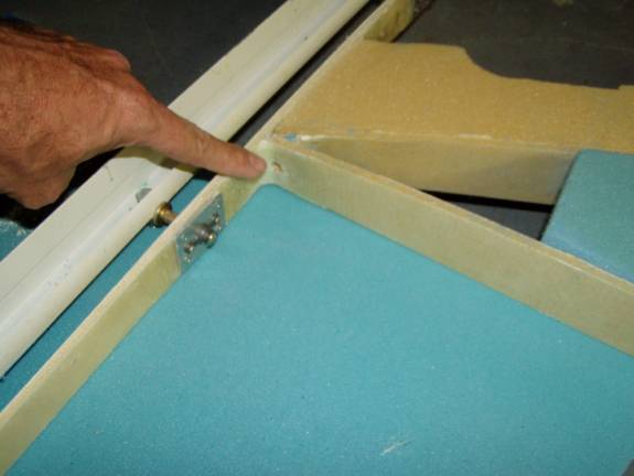
Hole for Antenna Cable
Drill a ¼” hole in the base of the horizontal rib as shown. The comm. Antenna cable will pass through this hole.
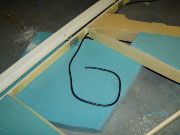
Routing the Cable
Measure out a length of 50 ohm coax cable, about 20 feet is sufficient to reach the radio. I used a shorter length, but will have to use an in line couple to reach the radio stack. Route the cable up through the hole in the lower rib. The cable will be secured in the corner of the lowest rib later. This will bring the cable forward.
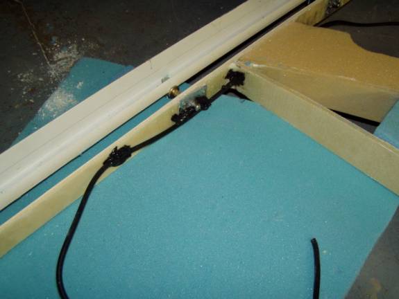
Silicon Sealer to mount Cable
Use silicon sealer to fill the hole and encase the coax where it passes through the ribs. Fiverglass is very abrasive and if there is any movement of the cable in the hole it will abrade. Pull the cable back and forth through the hole to insure it is completely coated with silicon sealer. Then use a couple of dollops of sealer to hold it to the rear spar. The cable will bend forward at the middle point between the two lower ribs.
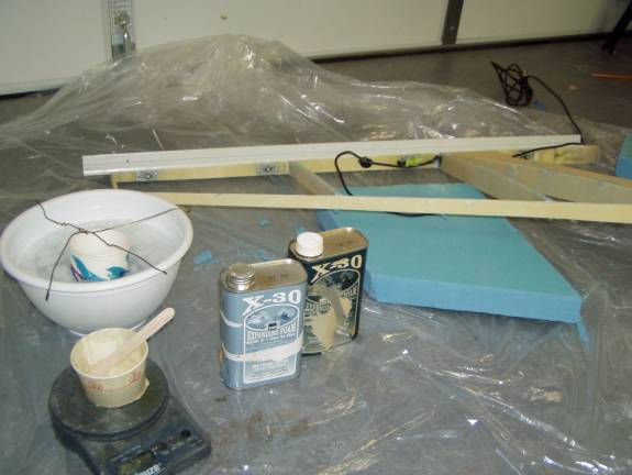
Preparing to Bond in Foam Blocks
Prepare to use expanding urethane foam to bond the foam blocks into vertical fin. Notice that I have used plenty of plastic drop cloth, I have my foam, my scale and mixing cup as well as the foam blocks arranged and my paint brush ready to go. Practice inserting the blocks into the vertical fin. Wrap a bit of masking tape around the hinge bolts so foam does not get into the threads of the hinge. Also I have prepared a bowl filled with ice water and a coat hanger arrangement to hold the cup in place. Mixing up the 2 part foam releases a great deal of heat and the foam can set up very quickly. If you use an ice water bath the working time is extended.
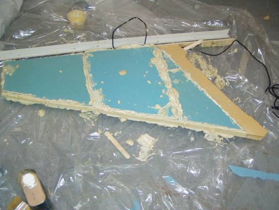
Foam Blocks Bonded In
When you mix up the foam, work quickly and paint both surface to be joined and insert the blocks. The foam cures quickly and you can then use a long sanding bar to sand the blocks and urethane foam down to the ribs. Don’t get to aggressive with the sanding, do not sand the ribs down. Listen to the difference in the sound of sanding the foam and sanding the fiberglass of the ribs.
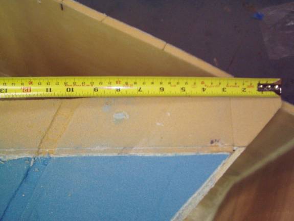
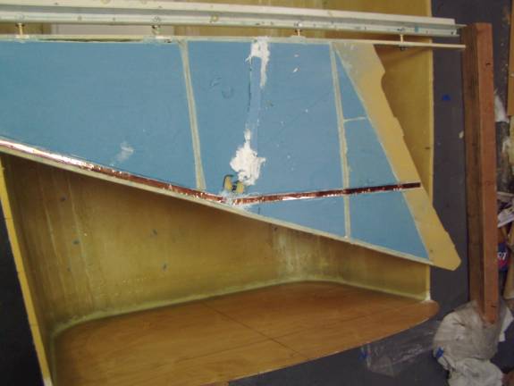
Placement of lower Copper Foil Tape
The antenna is made from two strips of copper foil tape. Each
strip is 20 3/8” long. Flip forward and view the next photos
to get an idea of what we are attempting to achieve.
the foam strips will be just under the fiberglass skin. The two
foil strips are not laid in place in a line, but are bent at an angle. This
prevents a dead zone in the capabilities of the antenna directly below
the aircraft. The bottom strip starts at the bottom of the fin
about 10” from the front as shown in the photo. Then continues
up out 20 3/8” to just behind the leading edge spar as seen in
photos to follow. Cut a slot for the copper foil about 1/8” deep
in the foam, also cut the slot through the ribs.
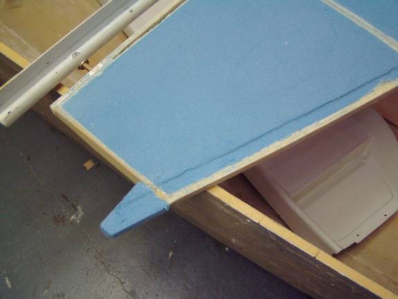
Position of Upper Copper Foil Tape
In order to get the 20 3/8” length of the top foil mounted in the vertical fin, we need to extend onto the foam above the top rib. Install and sand a small block to shape as shown in photos above. Don’t worry about the foam blocks size, you can make it over size or add to it later. Just insure that it is large enough to mount the antenna foil in.
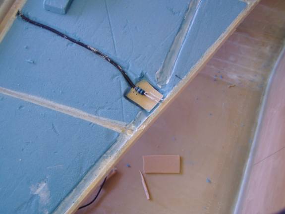
Proper Length of Coaxial Cable
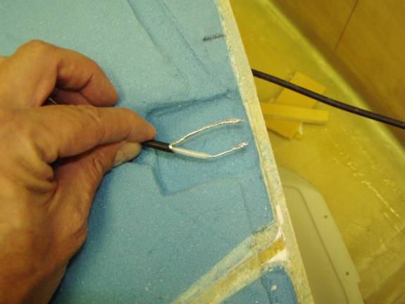
Pull the coax cable forward and cut it off at the front spar. Strip and twist the ends as shown. Cut a slot in the foam for the cable and a small area to house another little board that will support the cable/ foil joint.
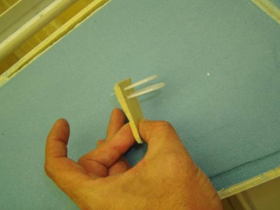
Terminator Block
Take a piece of scrap foam fiberglass laminate and cut it to fit in your little slot. Lay the cable onto it and mark several holes for twist ties to secure the cable.
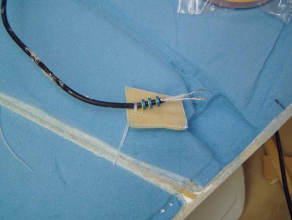
Placement of Ferrite Beads
Attach the cable to this little board with the twist ties and then slide the three ferrite beads into place. They need to be spaced about a ¼” apart close to the end of the cable as shown.
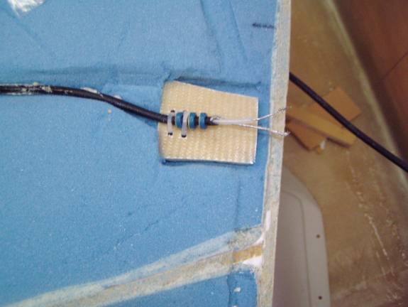
Installation of Terminator Board
Test fit the cable into position and insure that all parts of the assembly will end up being below the surface of the fiberglass skin.
Micro Slots for Foil Tape
Use a thin micro mixture to slurry the slots for the foil. Then thicken up the micro mixture and use it to secure our termination board and the cable into position. Again insure that all parts of the assembly will end up being below the surface of the fiberglass skin.
Placement of Foil Tape
Lay in the 20 3/8” inch pieces of copper foil tape. There should be a ½” gap between the two pieces of foil at our termination board.
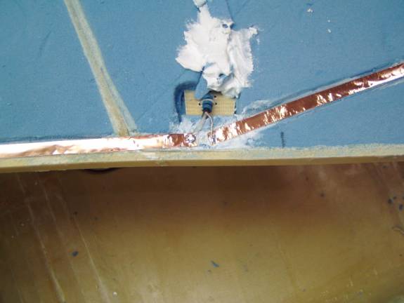
Soldering Cable to Antenna
Carefully solder the cable to the copper foil tape. Tin the foil tape first as well as the ends of the cable. Twist the shield together into a single unit. When soldering the wires to the foam do not dawdle and melt the foam to badly—but insure a good joint; we will not be able to get to it later. The internal shielded cable should be soldered to the foil pointing upward and the shield should be soldered to the foil strip pointing downward.
Use a thick micro paste to fill in the voids—cover the cable, fill in the space at the terminal board and cover the foil tape. Then carefully sand the vertical fin side flat again.
Secure the coaxial cable into the corner of the lower space and bring it forward. Then use a single BID layer to secure it into place.