Chapter 2 - Fabricating the Tail
Section 2 - Vertical Stabilizer
Assembling the Vertical Stabilizer
At this point you are ready to assemble the vertical stab frame. Refer to the 3D drawing to get an idea of how the parts fit together. The spars should already be labeled front and back and should have the locations of the ribs marked on them. Trial fit the parts together. The ribs will need to be trimmed slightly to allow for the slanting angle of the two spars.
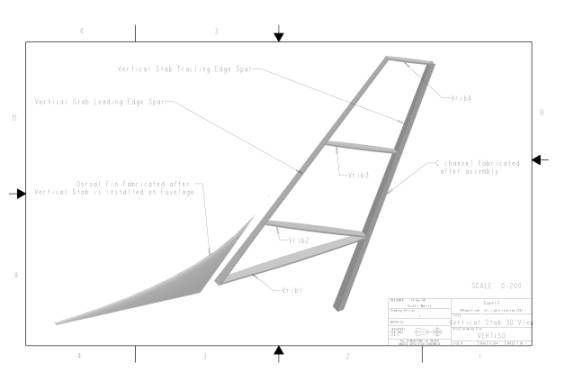
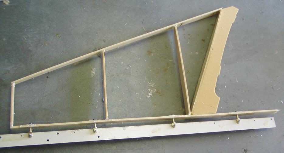
Notice how the two lower ribs come together at the rear spar. You can also refer to the photo at the very top of this page to get an idea of what we want to end up with.
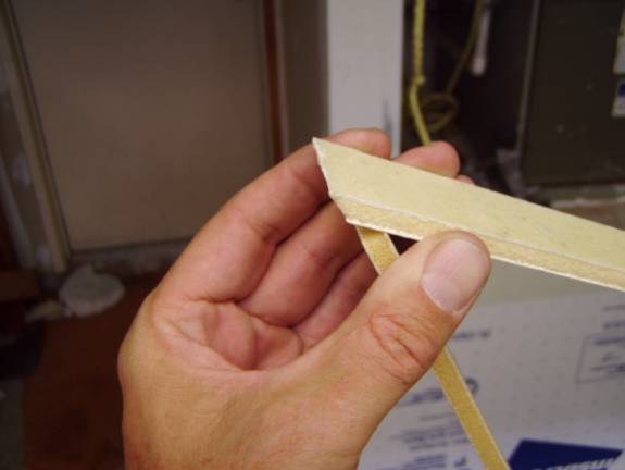
Notice how the forward spar is trimmed at an ange as it meets rib1, the lowest rib. Clamp the rear vertical spar to the work surface or to an angle as I did to insure the rear spar remains true. Once you have satisfied yourself that the ribs fit correctly, tack them into place with 5 minute epoxy or CA glue (super glue). Insure that the ribs are mounted 90 degrees to the rear spar.
Then add a small thick micro radius to the joints between the ribs and the spars. Finally use a 2 layer BID layup to join the ribs and spars to form the vertical stab frame.
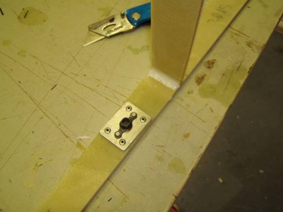
It is now time to reinforce the forward end of the vertical stab sides for the top elevator control cable pulley.
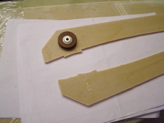
The above photo shows the approximate location of the upper elevator cable pulley that will be installed inside the vertical fin.
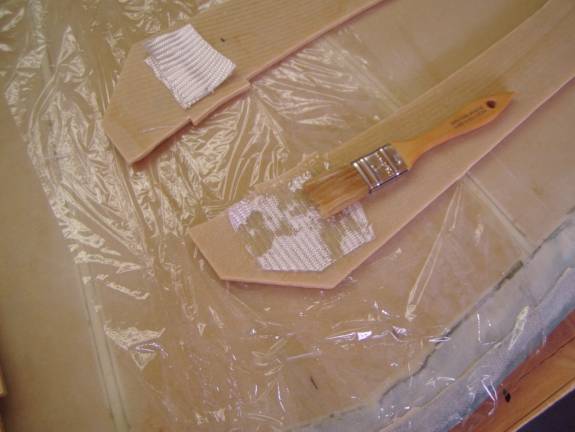
Apply two layers of BID on the forward inside side (glassed side) of the lower vertical stab sides in the area shown. Using your drawing of the vertical stab sides mark and drill 1/8" pilot holes in the locations for the pulley and the cable keeper. Drill these holes through both sides at the same time to insure the holes are lined up on both sides.
Position the two vertical sides into place below the bottom most rib and between the front and rear spars. Refer to the photo at the top of this page for the proper positioning of the sides. Remember to place the glassed sides in and the foam sides out. The sides need to be bowed outward to conform to the shape of the bottom rib. Use the vertical stab bottom rib as a guide to insure the correct shape for the sides. Do not attach the bottom most rib at this time, it is the large rib with the matching tabs to the sides notches. Use CA to tack the sides into place, remove the bottom rib. Use thick micro and a two BID layup all around the inside joint of the sides to the forward spar, rib1 and rear spar. Keep this neat as the elevator cable passes through this space. It is a little tight working on the inside, so take you time.
Next we will add foam to fill the spaces of the vertical stab, install the comm antenna and glass it.