Chapter 4 - Finishing the Tail
Section 2 - Building the Elevator
Trim Tab - Installation
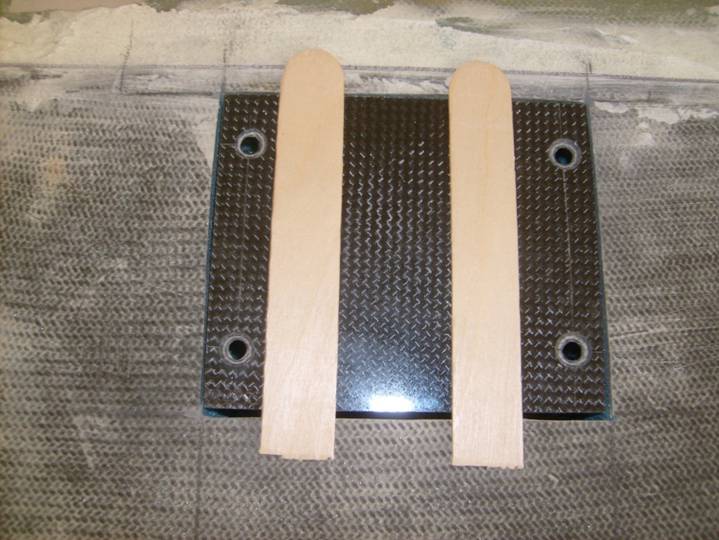
We are now going to bond the procured laminate mounting plates to the inside surface of the elevator skin. Temporarily bond two mixing sticks to the outside of the Servo Doo using a hot glue gun. See the following photo. Insure that it mounts flat to the surface of the elevator.
Aligning Cover Plate
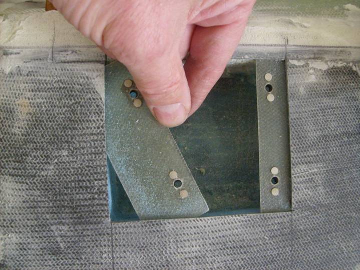
Test fit the mounting plates between the foam and the outer skin of the elevator. Be gentle so as to not disrupt the skin. Gentely remove the foam.
Installing Mounting Plates
Cover the servo cover in packing tape so it is not bonded to our mounting plates when we install them. Then use 5 minute epoxy and flox smeared into the foam slots, then wet the mounting plates with 5 minute epoxy where they will be installed under the carbon elevator skin and install. Wax four screws and install the servo cover. Let cure.
Nice work—the servo itself is now mounted.
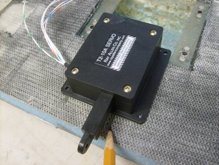
Next we will work on the trim tab. Position the Servo as shown in the following photo, squared between the mounting plates and square to the elevator spar. Mark the location of the sides of the servo arm on the elevator bottom skin. Extend these lines from the aft edge of the elevator to the servo door hole. This will give us an idea of the location of the control rod that will connect the servo to the trim tab.
Mark the location of the control linkage
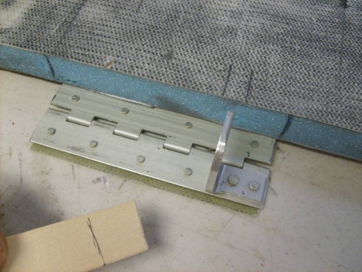
The hinges are bonded just under the top elevator skin. Refer to photos further down the page to get an idea of what we are working toward. The hinge with the control horn is centered between the two lines drawn in the previous step. Mark the blue foam on each side of the hinge to locate it.
Proper position of Control Horn Hinge
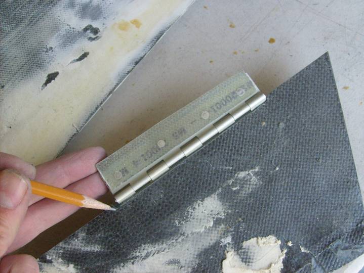
Make a mark on a mixing stick as shown in the next photo to establish the depth of the slot that will be cleared under the elevator skin for the hinges. Carefully scrape out the foam up against the underside of the upper elevator skin. Take your time and do not distort the skin. Test fit the hinge.
Mixing Stick used to scrape out Foam
The second hinge is located as shown below, 1.5” outboard of the trim tab notch. Mark this and clear the foam under the skin as was done on the first hinge. Scoop out the foam and test fit the hinge as was done with the first hinge.
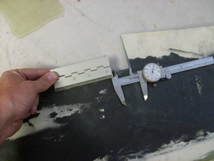
Location of the second hinge
View of the hinge installed under the elevator skin
Repeat the process of scooping out the foam on the trim tab and test fit the hinges on both the elevator and the trim tab.
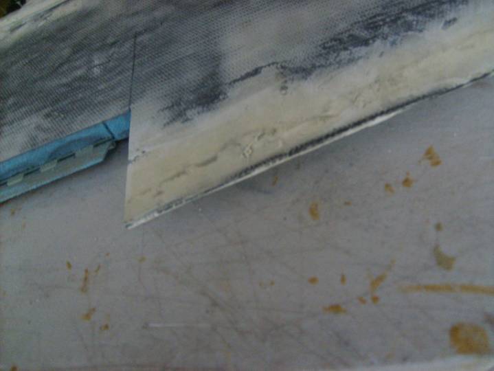
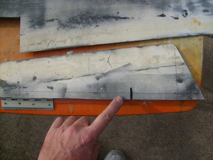
Position the trim tab using the aft edge of the elevator as a reference and the inboard edge. Mark the location of the hinges on the top skin of the trim tab and the elevator. Now using a cutoff wheel , carefully cut a notch as shown in the next photo, 3/32” into the skins to allow the trim tab to fit right up against the elevator.
Small notch for hinge
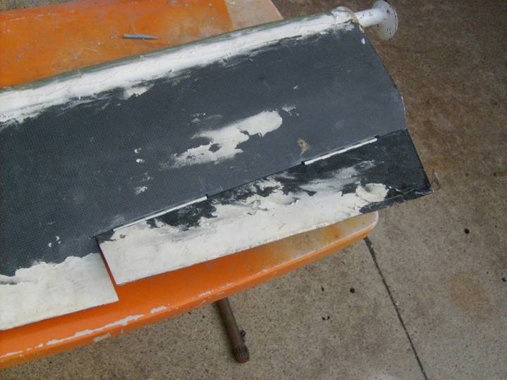
Flip the trim tab over and mark where the control horn hits. A small notch will need to be cut into the trim tab to allow for the control horn. Carefully position the trim tab on the elevator before cutting this notch as it will define the position of the trim tab side to side. Also draw a line ½” from the bottom edge of the trim tab as shown below. Cut this piece off.
Control horn notch and ½” line
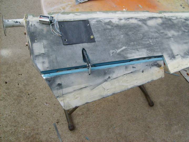
At this point we are ready to test fit the complete assembly. Obtain a 9V battery to run the servo in both directions.
The control linkage is simply a 1.5” 8-32 threaded rod (I used a cut off 8-32 bolt) threaded onto two Ray Allen Co Clevises.
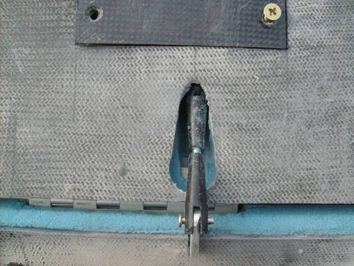
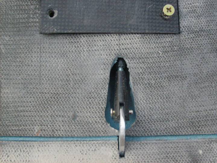
Flip through the following photos and get an idea for the slotted hole that has to be cut in the bottom skin to allow the control linkage to pass through. I started with an ½” hole just in front of the trailing edge of the elevator in front of the control horn, then used a dremel tool to slowly enlare the slot until it cleared the control linkage throughout all of the motion. You must also clear the pin that secures the clevis to the horn.
Trim Tab Full Deflection
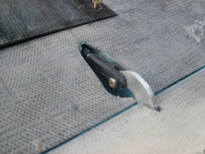
Close Up of extended Tab
Top View of Full Deflection
Close up of Opposite Deflection
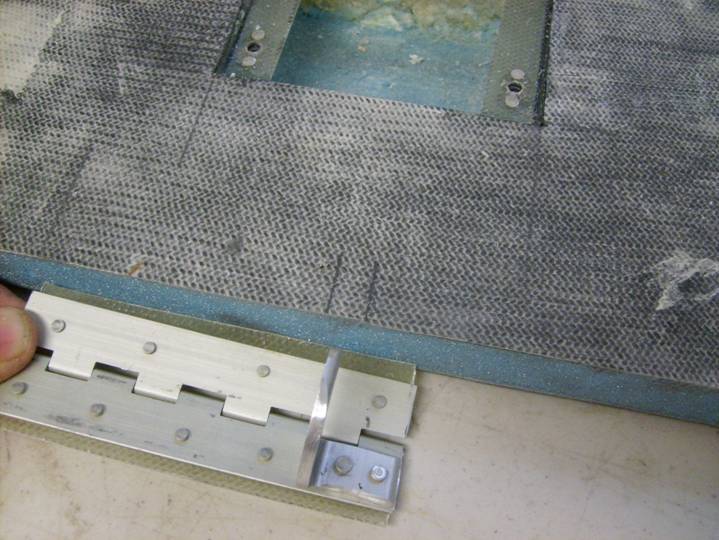
Use a single long hinge pin passing through both hinges to insure the hinges are co-axial. Coat the hinge pin with mold release wax. Develop a clamping method like the one show below to insure the trim tab is absolutely flat with respect to both sides of the elevator. Your goal is to return the trim tab to the position it held before you cut it free of the elevator. Mix up a mixture of epoxy and cabosil to a gelatinous consistency, you can use a little glass bubbles to thicken if desired. Use this to bond the hinges to the foam and upper skin. It is best if you bond one side of the hinges at a time, repositioning the trim tab and cleaning the ooze after each application.
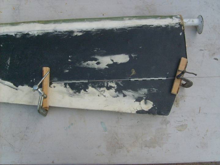
Clamp trim Tab in Place to Bond Hinges
Good Job, the trim tab is fully functional, next we will finish the assembly.