Chapter 4 - Finishing the Tail
Section 2 - Building the Elevator
Trim Tab - Parts Preperation
A trim tab is installed in the left elevator and is located on the aft inboard side. The tab is roughly 4.25” X 15” measured from the aft most point of the tab and the inboard driving rib. A Ray Allen Co. T2-10A servo is embedded in the elevator itself. This servo is nice in that it has the proper throw, is plenty strong for our application and has a built in position sensor. Start by drawing a straight line the length of the elevator at the forward side of the elevator spar on the bottom of the elevator. This line must be straight to insure the tab and servo door are square, but it is OK if you have to approximate the location of the front side of the spar.
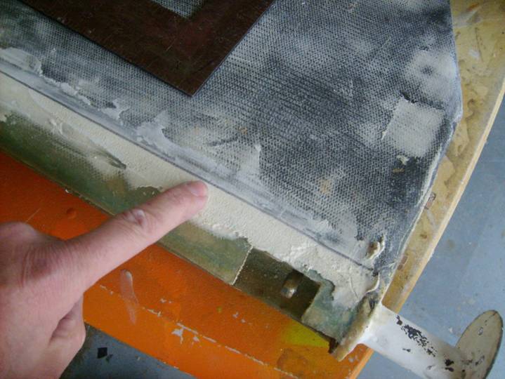
Line approximating the forward side of the elevator spar
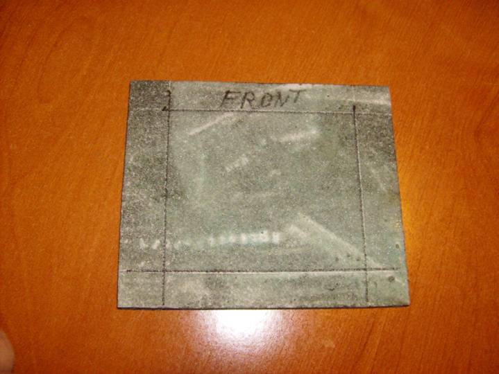
Next we will use this line to reference the servo door position. Draw two lines perpendicular to the elevator spar line, 4 inches and 8.25 inches from the inboard edge of the driving rib. Next draw two lines parallel to the elevator spar line, 3/8” and 3 7/8” aft. These four lines will define the location of the servo door which should be 4.25” X 3.5” with the long dimension running parallel to the elevator spar. Check one last time you are working on the BOTTOM of the left elevator.
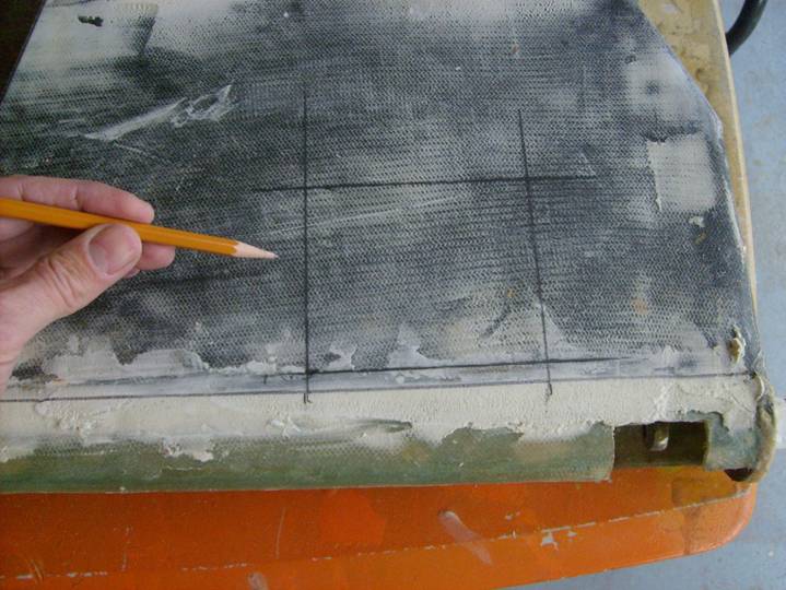
Trim Tab Servo Door Location
Next mark the location of the trim tab itself. Draw a line 7” aft of the elevator spar line and another line 15” outboard of the inboard edge of the driving rib.
Carefully cut out the Servo Door. Pay special attention that the cuts do not extend beyond the boundary of the door. Use a cut off wheel to cut the majority of the distance, but the last little bit should be cut with a broken hacksaw blade.
Carefully peel up and remove the door, careful not to crack it.
Carefully cut out the Servo Door
Next cut off the trim tab itself. Attempt to make a straight vertical cut all the way through the elevator. Remember the elevator is tapered to the rear and a vertical cut on a vertical table surface will not be vertical to the elevator true center horizontal plane.
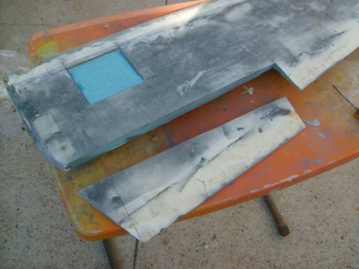
Trim Tab cut Away
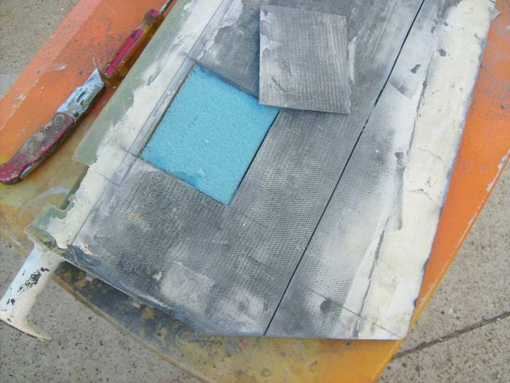
Slice out the foam under the servo door. Use the rounded end of a hack saw blade to insure you do not scratch or displace the carbon fiber skin on the opposite side.
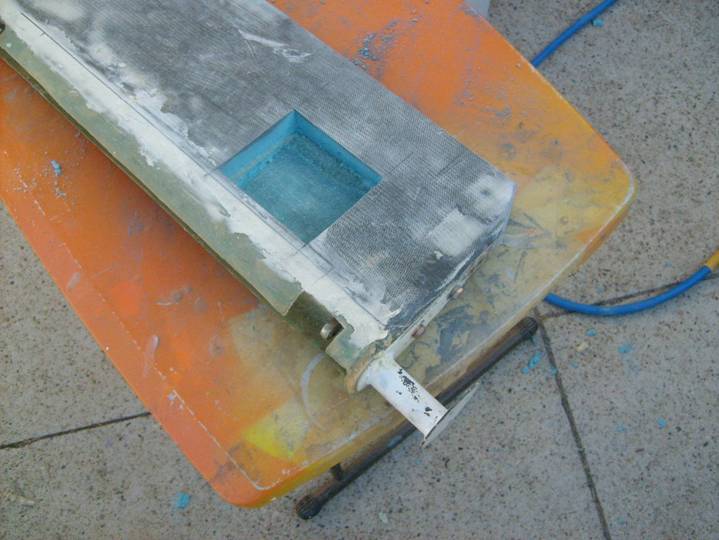
Foam removed from under Servo Door.
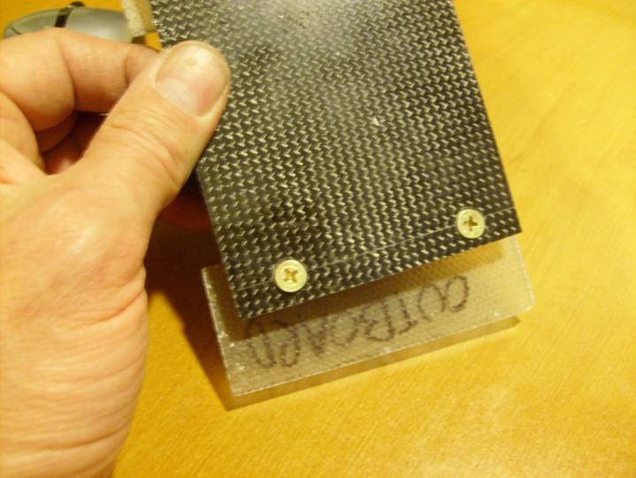
Next we need to pull together some parts. Procure the RAC T2-10A servo or equivalent, a 9” length of MS20001-4 hinge, 4 flat head 1032 screws and 4 matching nut plates (use MS24694S56 Screws and MF5000-3 Nut Plates). Prepare a 4” X 10” square of pre-cured fiberglass laminate. Use two layers of BID. I like to use a flat glass plane prepared with a layer of mold release to create these pre-cured laminates. Trim the cured laminate into 4 sections of .75” X 4.5” and two sections of 4” X 1.5”. Add two layers of carbon fiber to the servo door. I did this at the same time I created my procured laminate. Then trim to size. See the photo below. The four longer strips of precured flaminate are for the hinges and the other two are for the door nutplates.
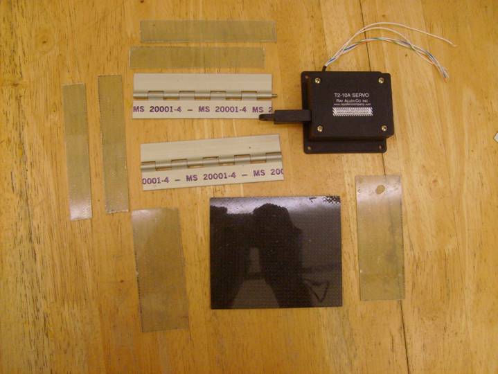
Some of the Parts Required for Trim Tab
The trim tab control horn is fabricated from a small piece of 1” X 1.5” X 1/8” 6061T6 aluminum angle. Print out the A sized flat pattern:
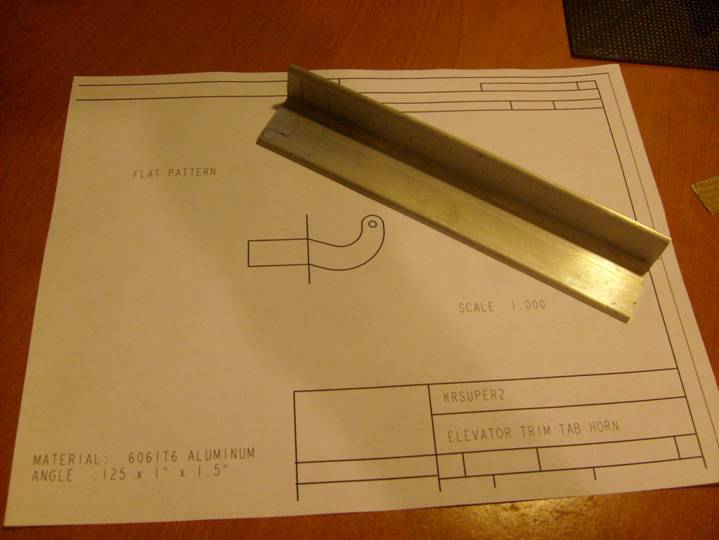
Control Horn Flat Pattern
Cut out the pattern and position it on the aluminum angle as shown below. Drill the 1/8” hole in the aluminum angle first, then position the flat pattern over the hole using and the line through the middle of the pattern to align with the corner of the alum angle. Cut, Grind and finish the trim tab control horn.
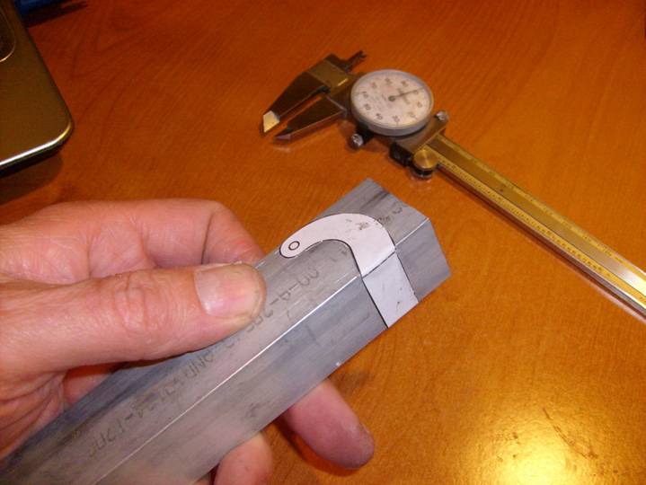
Flat pattern on Aluminum angle
The control horn is installed on one of the lengths of hinge as shown below. Be careful to align it with respect to the side of the hinge and the proper end of the hinge. Rivet it into place using 1/8” flat head rivets with the flat head of the rivets opposite the control horn, remember to counter sink the hinge..
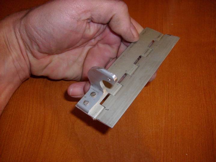
Control Horn mounted to hinge
Top Side of the Control Horn Hinge
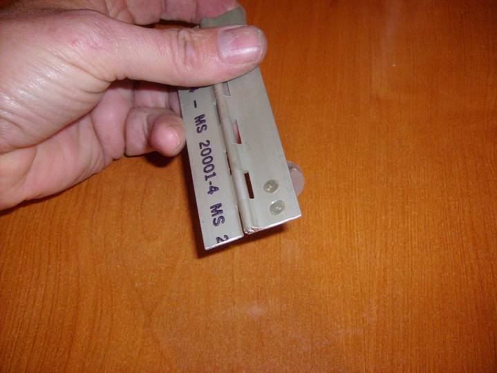
Using 3/32” flush rivets, rivet the longer procured laminates to the hinges as shown below. These laminate go on the side of the hinge that has the hinge pin. These laminates will separate the carbon fiber from the aluminum of the hinge. Remember, aluminum and Carbon fiber will corrode if brought into contact.
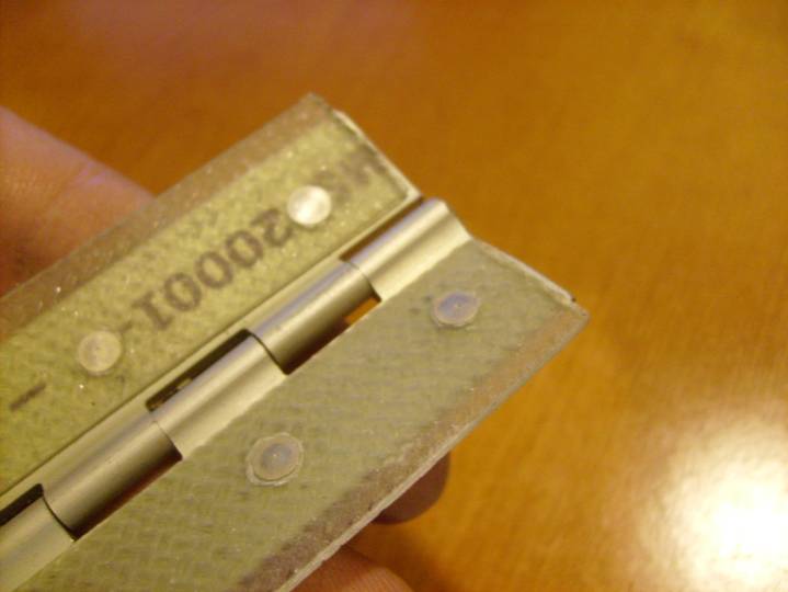
Precured laminate bonded in place
Good Job, we have finished the first hinge assembly. repeat the process for the second hinge, but without a control horn.
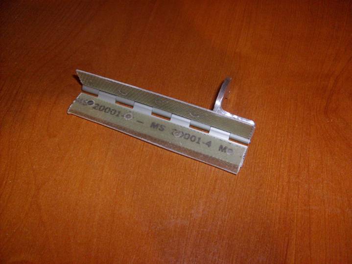
Completed Hinge Assy
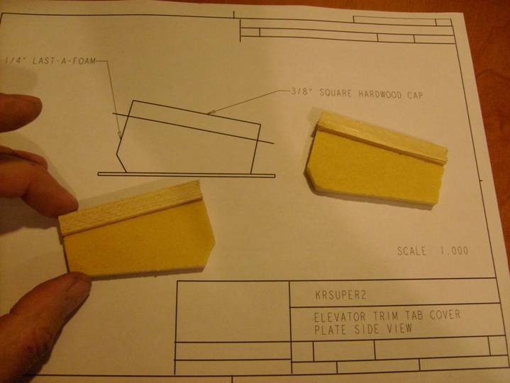
Next Servo mounts will be fabricated. Print out the following document. It is an A size 1:1 drawing of the servo cover and the servo mounts.
The mounts themselves are fabricated from a small piece of scrap ¼” last-a-foam and a length of 3/8” X 3/8” wood. I just cut down a piece of scrap spruce. The wood strips are flush with one side of the piece of foam. Make both a left and a right part as shown below. Note that the grain in the wood should be oriented so that they are horizontal, as if they were stacked up on the piece of foam. This will help prevent the wood splitting when we drill our pilot holes and install the mounting screws. Use 5 minute epoxy to bond the wood strips to the top of the foam servo mounts as shown in the photo below.
Servo Mounts
One of the servo mounts will require you to cut a small notch to allow the wires to exit from the servo. Carefully trim this out.
On the side of the servo mount where the wood extends above the foam, trim a small bevel in the wood to create a smooth transition from the foam to the wood.
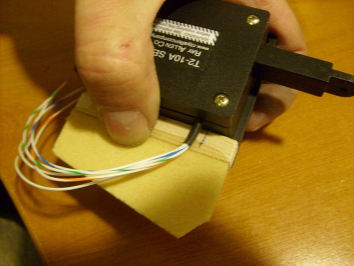
Marking the location of the wire Exit Notch
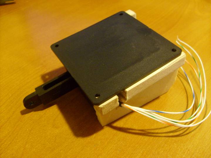
Completed Wire Notch
When happy with the Servo Mount sides, cover each side with a single layer of epoxy and BID. Let cure, trim to the edges. Then remove an 1/8” of foam around the three exposed areas of the mount.
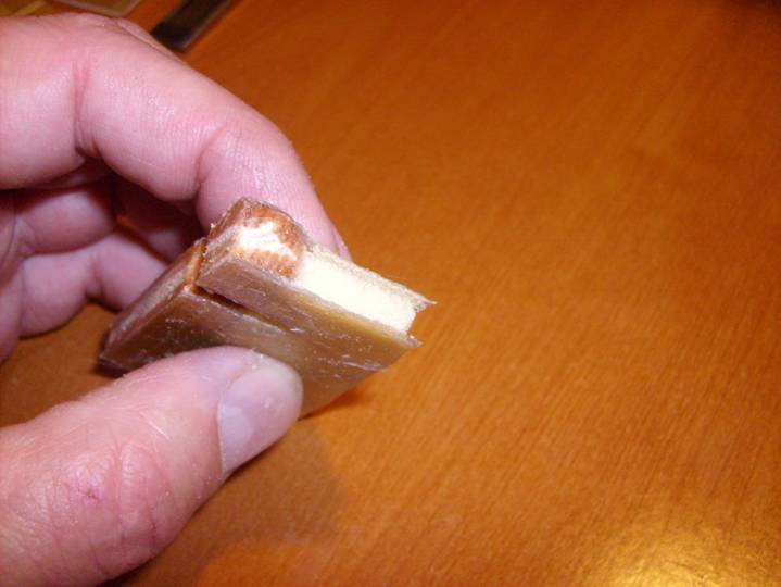
A bit of foam removed all the way around
Next we will mount the Servo mounts to the Servo door. Mark the inside of the servo door as shown below. The lines on the top of the door, or front of the elevator and back of the elevator (long dimension) are .5” in from the edge. The side lines are 5/8” in from the edge. Also mark the front of the door so it will maintain the proper orientation throughout the remaining steps.
Inside Servo Door Marked for Mount location
We are now ready to bond the Servo mounts to the inside of the Door. First apply two layers of masking tape to the sides of the servo to allow for a bit of room when we install the servo to the rails.
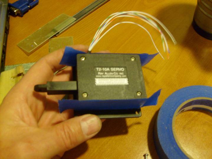
Spacer Tape
Place the servo on top of the two servo mounts and center it as shown below. The servo arm points down and to the back of the elevator. Drill pilot holes and install the small screws that hold the servo to the wooden rails. Insure the assembly is square and the servo is oriented correctly.
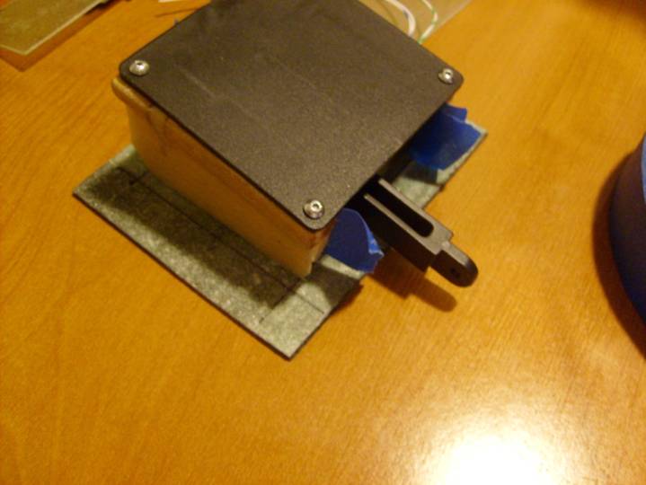
Servo assembly mounted on Servo Door
Use 5 minute epoxy and flox to bond the servo rails to the bottom of the servo door cover as shown above. Center the servo assembly in the square drawn on the inside of the servo door. When cured, use a single layer of BID to secure the bottom of the servo mounts to the door. This BID needs only extend 1/5" up the sides of the servo mounts and onto the servo door. Do not extend the layer up the side of the mount where the servo will mount.
Next we will drill the four mounting holes through the Servo door, these go on the sides, not the front and back. We do not want our mounting plates to interfere with the spar or the servo arm.
Measure .375” from the side edges of the cover plate, and 5/8” from the front and back edges of the cover plate. Mark on the outside of the cover door. Drill 1/8” pilot holes. Counter sink for AN507 screws.
Now grab the remaining two procured laminates and position them on the inside sides of the door as shown a couple pictures below. Line them up with the line drawn on the inside of the door
Match drill the two 4” X 1.5” 2 layer pre-cured laminate and install nut plates.
As you have done on the access panels, install nut plates using flush rivets.
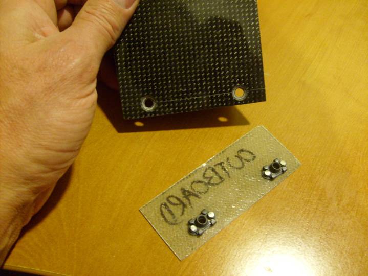
Mounting Holes and Mounting Plate
Mounting Plate Installed
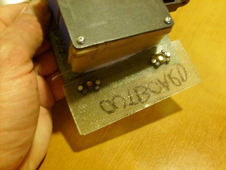
Mounting Plate Installed
Good Job, We are now ready to start installing the parts on the elevator.