Chapter 4 - Finishing the Tail
Section 2 - Building the Elevator
Elevator Leading Edge Radius
This step is a little tricky as we are now mating the rear flanges of the horizontal stab with a curved leading edge on the elevator. Our goal is to have a leading edge that mates nicely into the rear of the horizontal stabilizor, and gives us a small, constant gap through the full motion of the elevator. The steps include bolting a radius pattern onto the hinge points of the elevator, gluing blocks of foam to the leading edge of the elevator and sanding them to match the shapes of the patterns. We then mount the elevator to the horizontal stab and use a strip of sandpaper berween the horizontal stab flange and the elevator. By moving the elevator through its range of motion, and lightly sanding the forward foam to match we end up with a nice leading edge foam radius. OK Let us get started.
First print out the elevator forward radius patterns and cut the discs out of scrap thin plywood or masonite.
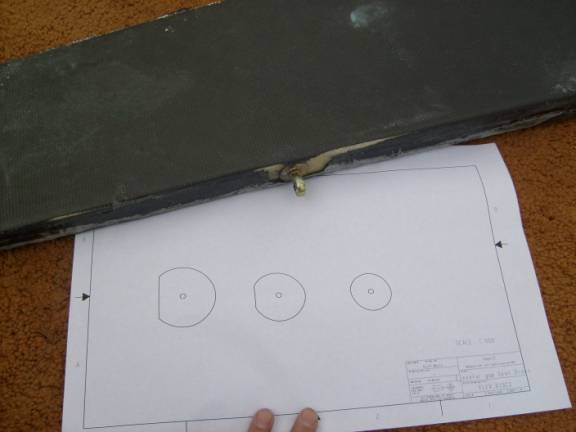
Pattern for elevatro radius templates.
Bolt these in place to the hinges. Larger one inboard and smaller one outboard.
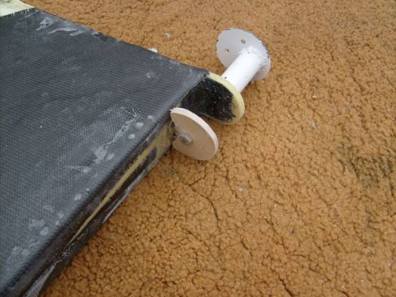
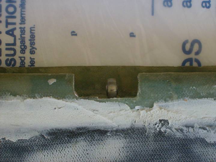
Disc mounted to elevator
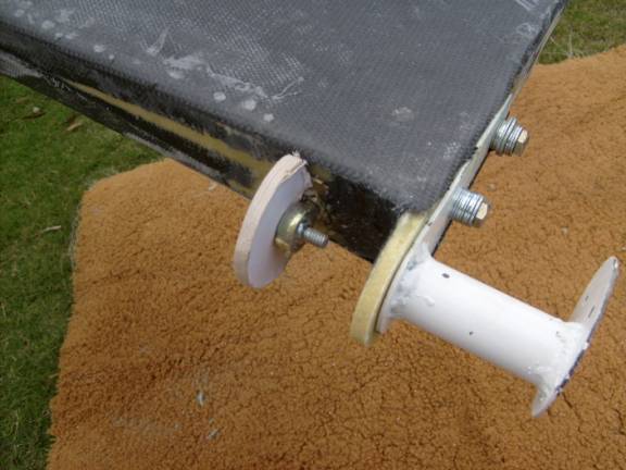
Disc mounted to elevator
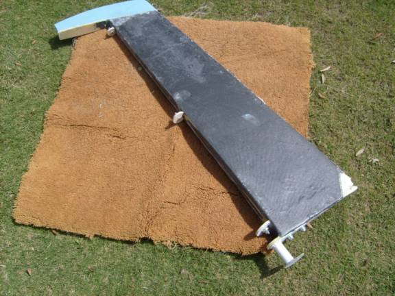
All three discs mounted
Next, bond 2" X 2" blocks of foam to the front of the elevator using 2 part polyurethane foam between the radius discs.
Bond the foam to the front of the elevators
Once the blocks are cured in place, Use a long sanding block to sand them to shape. Remove the pattern discs, you will have to remove some of the foam near them to accomplish this. Once this is done, we start the tricky part. But before we mount the elevator to the horizontal stab we want to double check the trueness of the horizontal stab flanges. They need to be straight and true as we aregoing to mate the elevator leading edge to them. If the flanges waver, it is a simple matter to use a heat gun to carefully soften them up and repossition them. Clamp them in the desired position while they cool.
Mount the elevator in place to the horizontal stab. This will be an iterative process as the foam will interfer the flanges on the horizontal stab, and the hinge bolts will be difficult to get at. Remember that we are mating two parts. You will need to sand the elevator foam to match the flanges, but you may need to again tweek the horizontal stab flanges as well. Move the elevator through its full motion and move a strip of sandpaper back and forth shapping the foam until you have an even gap.on both top and bottom though the entire range of motion of the elevator. Now use a sharpie to draw a line down interface of the flanges and the foam with the elevator at about 35 degrees deflection in each direction. We do not need a full radius leading edge only one through the normal range of motion. Good Job, that was the hard part.
Now remove the elevators from the airplane. We are going to apply a single layer of BID to the outside of the forward foam radius from the carbon fiber covered elevator to just beyond the line we drew in the previous step. First we will trim a triangular section of foam away from the intersection of the foam and the elevatro leading edge spar. This will give the glass something to attach to once the foam is removed. You do not need to slurry the foam as we will be removing it shortly. Now, add a single strip of BID the entire length of the leading edge, again the glass will run from the leading edge spar to just past our line drawn on the foam. See the following photo to see the resulting cured glass along the leading edge.
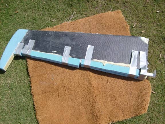
Forward edge Radius glassed on outside
Flip the elevator over and repeat this process on the bottom, glassing the forward radius section. Let cure. Finally dig out and remove all of the foam, leaving the glass radius sections top and bottm. Clean the back side of the BID section, apply a nice micro radius between the inside fiberglass and the leading edge. finally add another strip of BID down the length of the radius section on the inside. the glass should extend an inch onto the elevator spar, and the full width of the existing BID radius.
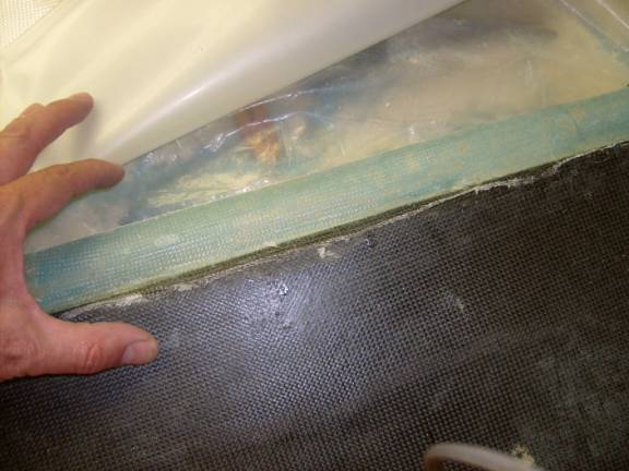
Clean inside of the BID radius
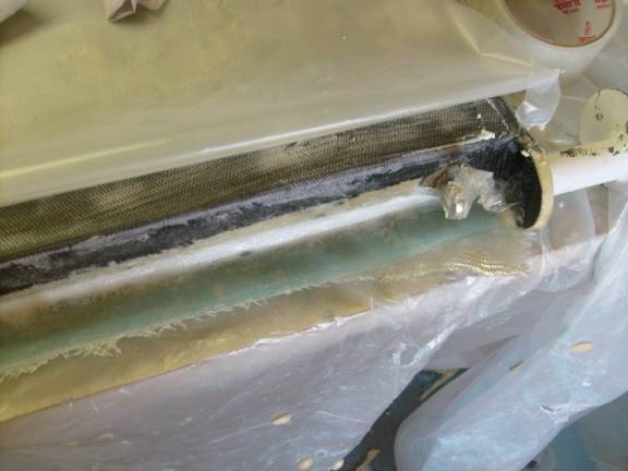
Glass the inside of the radius section.
Let Cure. Once the fiberglass is fully cured we will trim the radiused section along the leading edge of the elevator. Do a rough trim of the leading edge then install the elevator and trim the leading edge of the radius so it is always enclosed between the horz stabilizer flanges through the entire range of the elevators motion. You may need to use a heat gun on the radius sections to insure you have a constant gap along the intersection.
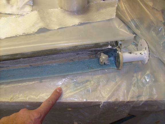
On the bottom radiused section cut out three notches as shown below to allow access to the elevator hinge bolts. These will also allow you to visually instpect the hinges during preflight. The notch extends from 1/2" inch on one side of the hinge to 1" on the other side of the hinge. The 1" dimention is for the nut and on the inboard most and outboard most hinges must be toward the middle of the elevator. The notch is deep enough to allow your tools to easily extend through the notch to tighten the attatching hardware when the elevator is held in its highest position.
Notch in the bottom leading edge of Elevator
Good Job, let us move on to the rudder clearance.