Chapter 4 - Finishing the Tail
p>Section 1 - Bonding the Tail to the Fuselage
Preparing Fuselage to Accept the Horizontal Stabilizer
Installing the horizontal stabilizer to the fuselage is an exciting milestone. The boat will really begin to look like an airplane. However, actually bonding the horizontal stab to the fuse is the easy part. First we have to prepare the fuselage to accept it--this will be accomplished in the following steps:
- Level the fuselage.
- Mark the location of the rear bulkhead and the rear of the horizontal stab on the fuselage.
- Trim top of rear fuselage to accept horizontal stabilizer.
- Fabricate and Install rear bulkhead.
- Postcure rear fuselage interior.
Step 1 – Level the Fuselage. The first step is to level up the fuselage. You should have a technique developed for this operation by this point. I use the lines we drew on the firewall to define in the roll axis of the fuselage and I use lines I have marked down the side of the fuselage to define the pitch axis. These lines were added when we bonded the fuselage halves together. Further I bonded a couple of ‘line levels’ to the fuselage to make it quick and easy to re-level the assembly. These are little levels that are intended to be hung on a string that I hot glued to several locations on the fuselage. They are quite effective.
Line Level Bonded on Fuselage Side for Pitch Axis Level
Line Level Bonded on Firewall for Roll Axis Level
Step 1 – Locate Horizontal Stab Position. Once the fuselage is level we need to locate a couple of key locations on the fuselage; the location of the horizontal stabilizer and the location of the rear bulkhead. The rear edge of the horizontal stabilizer is located at 169 7/8” from the firewall and the front side of the rear bulkhead is located 155” from the firewall. When measuring these distances it is important to stabilize the firewall. A good way to do this is will a 2X4 clamped to it in a similar manner to the way a 2X4 is clamped to the bulkhead in the above photo. If you do not stabilize the firewall you will notice that it will flex aft as you pull your tape measure tight. You want an accurate and repeatable measurement to these two critical points.
Step 2 – Print Template. Print the two rear fuselage template sheets (Sheet1 and Sheet2) and tape them together to create the full size sheet as shown below. Cut out the fuselage portion. This is a special template created from a view normal to the fuselage side, not to the centerline of the aircraft. That is, the dimensions only make sense once the template is taped to the side of the fuselage.
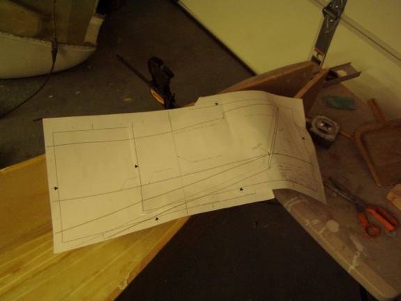
Full Size Rear Fuselage Template Sheet
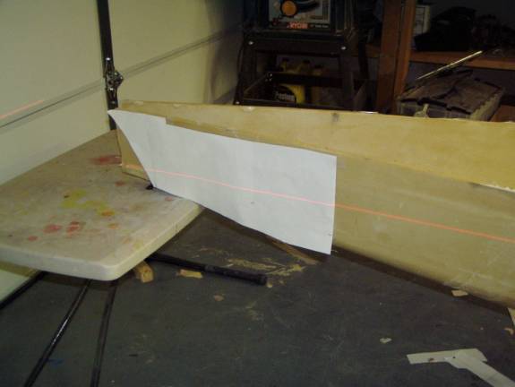
Step 3 – Tape Template to Fuselage Side – Affix the template to the side of the fuselage as shown below using the location of the rear side of the horizontal stabilizer and the level line. The level line marked on the template should be level with the horizontal line on the firewall. Use your laser level to align this as in the photo below. Re-level the fuselage if needed to get the template to be positioned as shown. If you do need to re-level to get the template to be placed properly, reset your permanently placed line levels as we will be precisely adjusting the horizontal stabilizer incidence angle in the process and the rest of the construction will be referenced to the level line we define now.
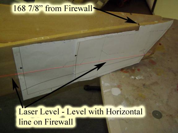
Proper Position of Template
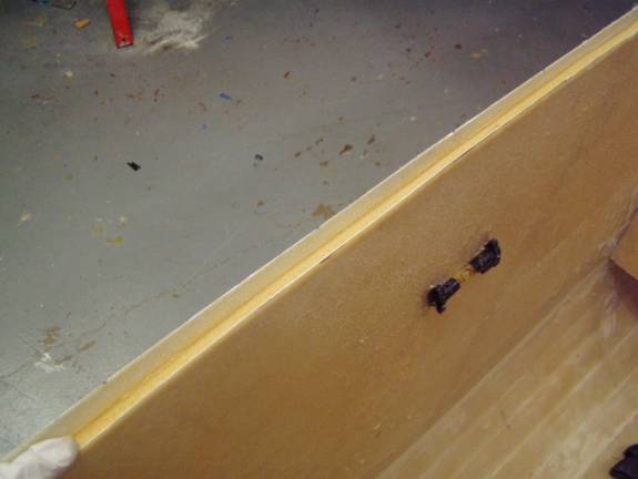
Step 4 – Mark Horizontal Stab Position – Mark the material to be removed from the fuselage side as shown below. Also mark the rear section of the fuselage to be removed for the vertical stabilizer. This step is not shown in the accompanying photographs, but this is the best time to do this.
Template positioned on Co-Pilot side of fuselage
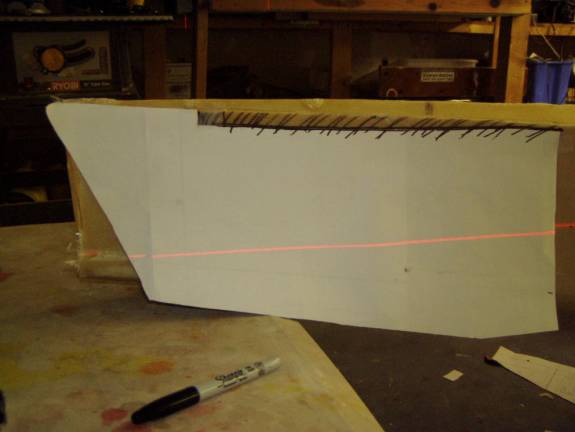
Mark Material to be Removed for Horizontal Stab
Step 5 – Remove material from fuselage to create shelf for Horizontal Stab – Remove the material that was marked in the previous step. Also remove the material aft of the template as this is for the vertical stab. This step is not shown in the photos, but should be done now.
Remove Material
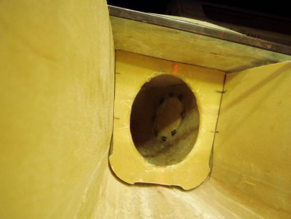
Step 6 – Fabricate Rear Bulkhead – Print out the full size template for the rear bulkhead and cut out a bulkhead from ½” thick 4.5lb. last-a-foam. Cut out the center section and radius the edges of the center hole. Notice that the large hole in the center has small ears cut out near the bottom, these are to provide additional clearance for the rudder cables and are not reflected in the bulkhead in the photos (yet). Layup a one layer BID on each side of the bulkhead, smoothing the glass around the radius in the center hole. I will not detail how to do this as you are an expert at fiberglass layups by now (vacuum, slurry, etc.).
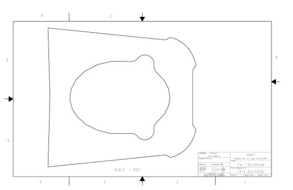
Rear Bulkhead Template
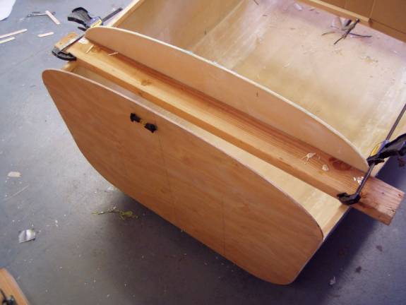
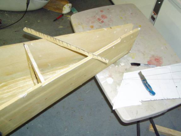
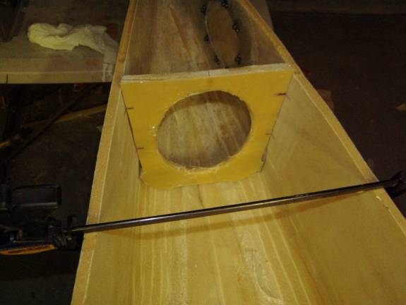
Step 7 – Position Rear Bulkhead – Position the rear bulkhead as shown in the following two photos. You will need to trim the bulkhead so it tapers to the rear in order to get a good fit with the fuselage sides. Its position is defined by three constraints: (1.) its forward edge is 155 inches from the front of the firewall. This was marked in an earlier step on the fuselage. (2.) Its top rests against the bottom of the horizontal stabilizer while it is sitting on the fuselage. (3.) It is level vertically-use a small carpenters level to insure this. Once it is properly positioned, draw a line along the front edge onto the fuselage and make a couple of alignment marks as shown to allow you to position it correctly.
RearBulkhead in proper position against Horizontal Stab
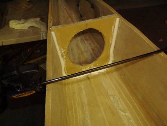
If required, use a clamp as shown below to pull the fuselage sides in against the bulkhead.
Bulkhead properly positioned and clamped.
Step 8 – Bond Rear Fuselage in Place – Once the rear bulkhead is positioned properly, bond it into place. Use thick micro to create a radius and fill all gaps between it and the fuselage. Then layup a two BID strip of fiberglass on both sides of the bulkhead/fuselage joint, insuring the overlap is at least and inch and a half on both sides. Let cure.
Thick Micro Radius and Fill Joint
Step 9 – Post Cure Fuselage interior – This is a good time to post cure the fuselage as it is still a manageable size and all interior bonds are complete. I performed this by simply covering the fuselage with a sheet of 1” thick polystyrene insulation board and heating the inside with a heat gun. A thermometer was used to monitor the temperature.