Chapter 3 - Fuselage
Section 3 - Joining the Fuselage Halves
Installing the Seat Back
The Super 2 Seat Back also functions as a structural bulkhead, but unlike the other bulkheads, is removable. The seat back is a piece of 1/2" lasta-foam with a reinforcement strip along the top. It is secured to the aircraft with flanges mounted to the fuselage sides.
Step1: Print out a copy of the seatback drawing and transfer the dimensions to a sheet of ½" 4.5 lb. Last-a-foam. The drawing provides the dimension of the seat back as well as a 1:1 pattern for the curves at the top of the seat back.
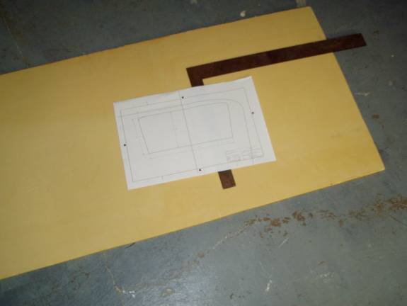
Seat Back Drawing
Step 2: Layup front side. Slurry and layup fiberglass on the front side of the seat back. Use one layer of UNI running side to side, then a layer of BID on the 45 degree bias.
Step : Sand the side edges of the seat back so the layup on the back side can curve around the edge and meet the layup on the front. This will seal the edge of the seat back. Layup a single layer of BID on the back side of the seat back.
Step: Trim and clean up seat back to final dimensions.
Step: Cut two pieces of wooden 2X2s 14” long.
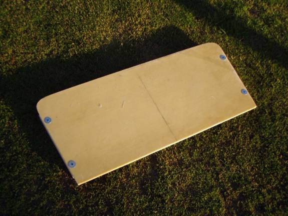
Wood Screws through fender washers secure 2X2s
Step : Mount the 2X2 blocks even with the edges of the seat back on the forward side as shown in the two photos. Use sheet rock screws through fender washers to hold the blocks in place.
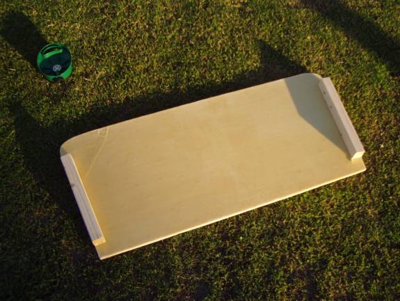
2X2s mounted on front side of seat back
Step : Draw two lines on the inside fuselage sides to mark the location of the seat back. Level up the fuselage and make a mark on the top of the fuselage side 60” back from the firewall. Draw a 60 degree line, sloping forward, on the inside as shown below.
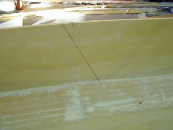
Mark on fuselage showing position of front of seat back
Place packing tape on the backside of the seatback to act as release film covering at least three inches from the edge.
Position the seatback into the fuselage with the front side aligned with the mark on the fuselage. Use a couple of wood screws and fender washers through the fuselage side to secure the seat back into its proper position. Mark the seatbacks position with respect to the fuselage so it can be positioned properly later when the wood blocks are removed.
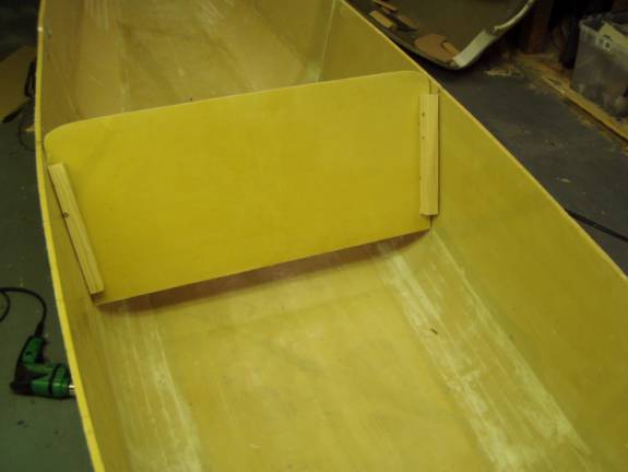
Seat Back mounted in position.
Step : Prep the fuselage side for a flange by roughening up the fiberglass with coarse sandpaper and clean the surface with acetone.
Create a 4 layer laminate behind the seatback and the fuselage side extending at least 1.5” onto the fuselage and 2.5 inches onto the seatback.
Create Flange layup
Once the flange has cured, remove the seatback and trim the flange to 2” wide. Trim the top and bottom of the flange as well. The bottom should be trimmed about a half inch above the bottom of the seat back and the top should be trimmed about 1.5” down from the top of the fuselage sides.
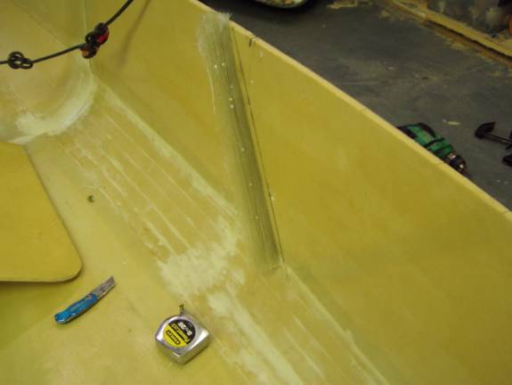
Resulting seatback flange
Step: Once the flange is trimmed to the proper size, fill the front corner between the flange and the fuselage side with a radius of thick micro.
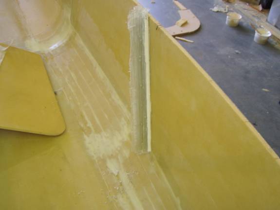
Thick Micro Radius
Prep the fuselage side in front of the flange as well as the flange itself as before for a layup.
Layup 3 layers of BID between the flange and the fuselage side on the front side of the flange.
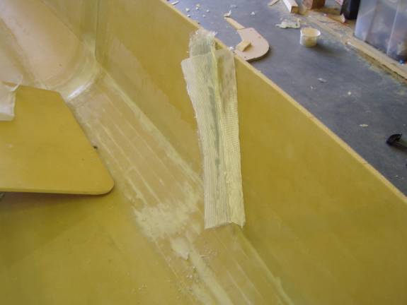
Front Flange layups
Notice how the layers of fiberglass are staggered in width where they lay against the fuselage side.
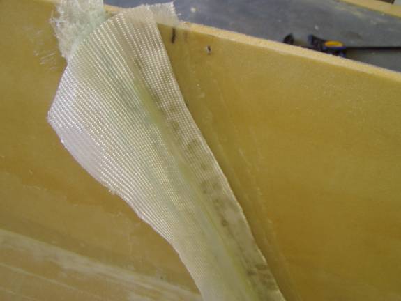
Stagared layers on Fuselage Side
Remove excess resin with a paper towel and let cure.
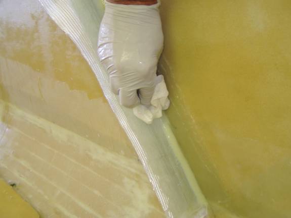
Remove excess Resin with Paper Towel
Once the flange has fully cured, trim it to size.
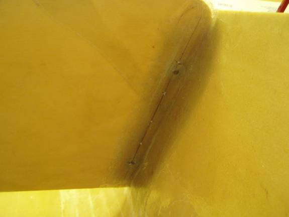
Draw a line down the front side of the seat back 1 inch from the edge. Drill 5 3/16” holes evenly spaced down the side as shown below. The first hole should be about 4” from the top of the fuselage and the rest should have about 2.5” spacing.
Reinstall the seatback into position against the flange using the marks created earlier. Drill the holes through the flange, inserting screws through each hole to maintain the seatback in its proper position as each additional hole is drilled.
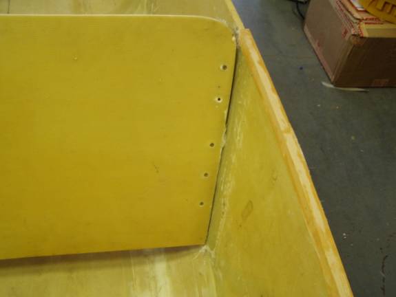
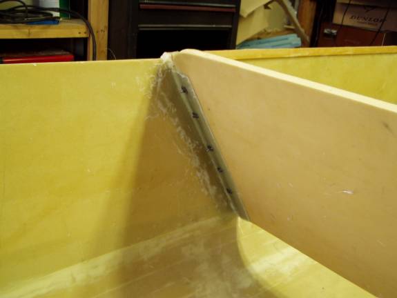
Seatback Mounting Holes
Install nut plates on the rear side of the flange at each hole location. Refer to the construction of the rear access panel if you need instructions as to how to install nutplates.
Nut Plates installed on rear side of Flange
Install wooden reinforcement buttons in the seat back at all ten hole locations. Cut the glass from the rear and cover the buttons with 1 layer of BID.
Redrill the holes and counter sink the front side of the holes so the screws mount flush with the forward surface of the seat back.
Install the screws to secure the seat back into position..
Cut a piece of ¼” thick last-a-foam 3 inches wide and 45 inches long. Layup a one bid on one side.
Trim the top of the seatback front side fiberglass laminate so a level surface exists as shown below.
Once the 3 inch wide strip has cured, roll the edges around a bottle as shown to create the edge radius.
Tack the strip of last-a-foam into place along the top of the seatback, glass side up, extending rearward. Bend the ends to match the curve of the top edge of the seat back. Trim the ends with a pleasing curve.
Layup a one BID layer of glass on the underside of the seat back top strip extending it around the rear edge and onto the top.
Layup a strip of BID along the front top corner between the seat back top strip and the seat back.
Cut four triangles of ¼” last-a-foam to act as supports to extend the length of the seat back top strip and about 2” down the back side of the seat back. Tack these into place evenly spaced along the top of the seatback as shown.
Slurry these reinforcement triangles and cover them with one BID.