Chapter 3 - Fuselage
Section 4 - Fuselage Features
Elevator Bellcrank
The elevator control system consists of a stick assembly mounted under the seat, which is attached to an elevator bellcrank mounted at the aft end of the control tunnel. There is a push rod attaching these with a rod end at both ends. The bellcrank then has two elevator cables that run back to the elevator itself. The top cable runs up over a pulley in the vertical stabilizer in order to clear the horizontal stab. The lower cable is a straight run back. There are turnbuckles in the cables to adjust the proper up and down deflections and allow for proper tensioning of the system. There are two bolts that pass through the control tunnel that the bellcrank hits up against at both ends of it travel that act as elevator stops.
The elevator bellcrank is made from 1/16" 6061-T6 aluminum sheet and a BC4W10 (AN218-4) bellcrank bearing. To start, print out a couple copies of the elevator bellcrank drawing. This is a full scale 'flat
pattern' drawing, meaning that you print two of these and glue them to a sheet of 1/16" 6061-T6 aluminum sheet. Then cut them out. There are double lines where the parts are then bent to form the two sides of the bellcrank. Use the BC4W10 (AN218-4) bellcrank bearing. This is riveted into place using AN470AD4-7 rivets.
First, clamp the bearing centered in the larger hole. Match drill one rivet hole through the aluminum. Use a cleco to hold the bearing centered, then drill another hole on the other side of the bearing. Again cleco the new hole and drill a third hole. Now, clamp the other bellcrank side into place and match drill the three holes into the other side insuring the bellcrank is properly aligned. Use clecos in these three holes and finish drilling the rest of the rivet holes. Then rivet.
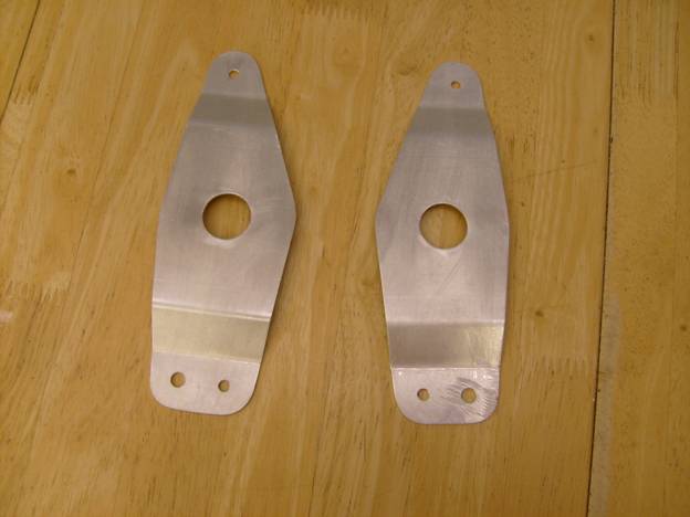
Bellcrank Halves cut out – mirror images of each other
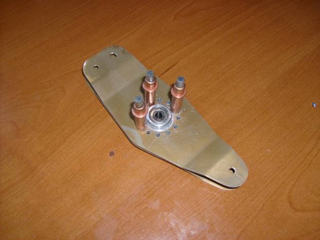
Cleco and match drill rivet holes
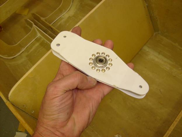
Finished Bellcrank
The finished bellcrank has three holes, two smaller ones and one larger one. The larger hole is mounted down and toward the front of the aircraft. A rod bearing is bolted here with an AN4 bolt and connects to the elevator control tube that will attach to the control stick. The two smaller holes will have AN3 bolts with castle nuts and cotter pins through them. Shackles will then attach to these bolts and in turn the control cables for the elevator.