Chapter 3 - Fuselage
Section 4 - Fuselage Features
Rear Control Tunnel
The rear control tunnel encloses the rudder cables and elevator control tube that pass down the center of the aircraft and would otherwise be exposed through the baggage compartment. Wiring for the elevator trim, position lights, antenna cables as well as the static line also run down through the control tunnel.
By this point in the Super2 construction you are quite familiar with the construction techniques employed. I no longer need to be as explicit in the details of constructing each part.
Print out the drawings for the rear control tunnel sides and create a full sized template. There are four drawings that need to be taped together at the vertical reference lines.
Create a left and right side using ¼” last-a-foam with one BID on each side. Drill the three pilot holes in each part.
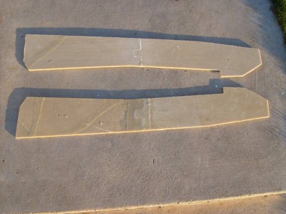
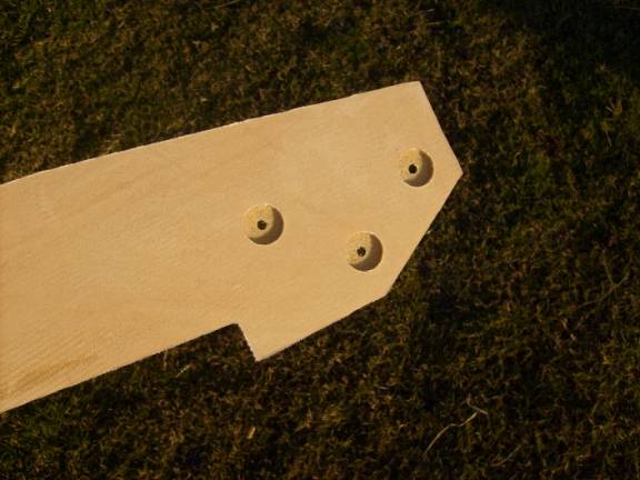
Rear Control Tunnel Sides
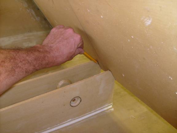
Notice that there are three holes located on each part toward the rear. The center of these is the pivot point for the elevator bellcrank. The remaining two holes are for through bolts that act as control stops for the elevator.
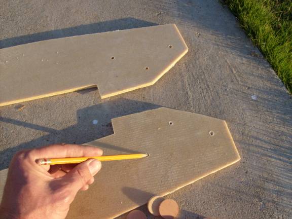
Rear Hole Locations
Mark the two sides so you don’t end up making two right sides.
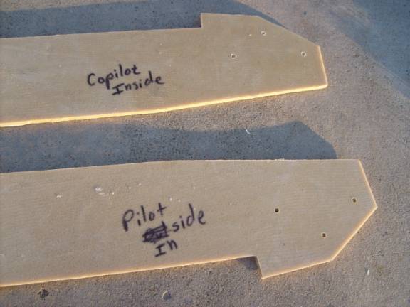
Identify each Side
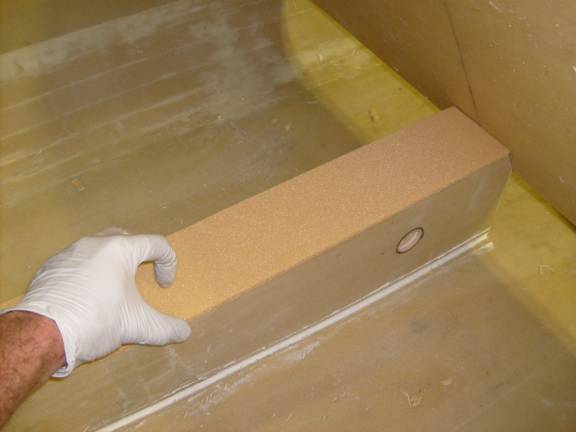
Reinforce the rear holes with wooden buttons using the technique we have already mastered.
Reinforcement Preparation
Cut a couple 3” spacer blocks from scrap 2X4 and place between the control tunnel sides.
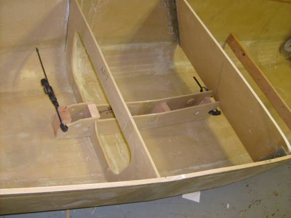
Control Tunnel Installation
Position the rear control tunnel inside the fuselage. The forward edge should contact the very bottom of the seat and the rear sides of the control tunnel should fit into the slot of the baggage bulkhead. The control tunnel should be centered down the middle of the fuselage.
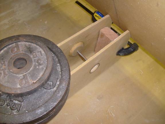
Close up of 3” spacer Block
Note: There is a pivot point shown in the above photo that is no longer used. This was a mounting point for the rudder cable pulley that has been moved forward in the final design. Please disregard any visual reference to this feature.
Use CA to tack the control tunnel into position. Tack it to the baggage bulkhead and the floor of the fuselage. Do not tack the control tunnel sides to the seat back.
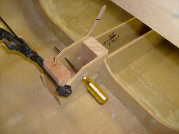
View of Aft end of Control Tunnel
Remove the spacer blocks and secure the control tunnel into position with a single layer of BID along the interface to the fuselage floor and the baggage bulkhead. Remember to clean the surfaces and apply a micro radius. Do not bond it to the seat back Let cure.
Mark the seatback where the inside of the forward edge of the control tunnel sides met it as shown below. We will need to remove a section of the seat back to allow the elevator push tube to pass.
Mark tunnel contact on Seat Back
Fabricate the control tunnel top by starting with a 3.5” wide piece of ¼” last-a-foam the full length of the control tunnel. Layup a one layer BID on the bottom side of the foam.
Trim the edges of the resulting part to match the sides of the control tunnel. Sand a radius along the sides of the top.
Apply packing tape along the top sides of the control tunnel as a release film. Layup a one BIB fiberglass over the top of the control tunnel lid and overlap about an inch onto the control tunnel sides. Let cure.
Remove the control tunnel lid and trim the resulting flanges to an even 1”. Remove the packing tape from the sides of the control tunnel.