Chapter 3 - Fuselage
Section 4 - Fuselage Features
Rudder Pedals
Before we can start work on the rudder pedals we need to determine their best location. I am a tall guy, 6' 3", so the Super2 will accommodate a wide range of pilot heights. The seat location should not be moved as the aircraft Center of Gravity was designed around the pilot in that location. If the aircraft is to be built for a shorter pilot, the rudder pedals should be moved aft, maintaining the pilot sitting position. If it is desired to have an aircraft for a range of pilot heights, it is best to place the rudder pedals to accommodate the tallest pilot, then use a seat cushion at the seat back to move the shorter pilot forward. It is required that W&B is performed for all pilot configurations that the aircraft will be flown.
The first thing we will do is model the pilot sitting position to properly place the rudder pedals. At this point your seat back should already be installed and we will be able to sit in the fuselage and try the sitting position on for size.
A Note of Caution: Extreme care needs to be exercised when getting into and out of the fuselage at this point in its construction. It is not fully stabilized structurally and a single foot bearing the full pilots weight at a single point on the fuselage bottom can damage the fuselage. Be very careful and enter gingerly, use your hands to support your weight on the fuse sides and be conscious of point loads on the airframe. The fuselage should be resting on the ground and should be supported under the seat area.
The Super2 was designed assuming a 2" thick seat cushion at the seat back and the seat bottom. We will first install a pseudo spar to emulate the location of the spar box, through which the wing spar passes through the fuselage. We will then place a three inch thick box/crate or other spacer to emulate the seat bottom. Then we will use pillows or available seat pads to emulate the desired seat cushions. At this point the pilot can enter the aircraft and model the desired seating position and thus the desired rudder pedal position.
A heel rest, or secondary floor will be fabricated from ¼” last-a-foam, reinforced where a set of pivot blocks will be installed and then mounted in the fuselage on a series of standoffs. The rudder pedal weldments will be fabricated from 4130 steel tubing and the actual pedals will be made from aluminum angle.
Let us pull together the material we will need for this step:
- 9 feet - 4130 tubing ¾” OD X .058 thickness – ACS 03-04500
- ¼ square foot Nylon Plate ½” thick – ACS 03-51300
- 2.5” X 4” X 1/8” 6061T6 Aluminum angle – ACS 03-48675
- 2 or 4 (depending upon co-pilot brakes)Brake Cylinders – Matco MCMC-4 ACS 06-11100
- ¼” thick sheet of 4.5 lb last-a-foam
- Nut plates
- An3 hardware
- ¼” plywood hard points
We will need the following drawings:
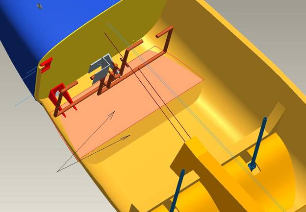
Let us start with the heel rest. Take a sheet of ¼” last-a-foam and cut a piece that is roughly 12” by 35”. It will have to be trimmed to the curvature of the bottom of your fuselage. You are aiming for a heel rest with its forward edge 3 inches back from the firewall and touching the fuselage bottom. It will then be level in both horizontal directions. This will result in the rear edge being about 2.5” off the floor. A second piece will be fit to make a 45 degree angle to close off this open section to the rear. Slots will have to be cut in the front to clear the motor mount brackets. Below is a picture of the inside forward fuselage section with the heel rest highlighted. Cut four triangular pieces of ¼” foam with 1 BID on each side trimmed to act as supports for the heel rest. These will be bonded to the fuselage floor on edge and support the heel rest.
Once you are happy with the fit of the heel rest, apply one BID to each side. Bond the four triangular supports to the fuselage floor, but do not bond in the heel rest at this time. Remember how we created a glass support for the horizontal stab on the rear of the fuselage? We will create the same thing for the heel rest on the four triangular supports. Once the supports are bonded to the fuselage bottom; they can be tacked into place with cyanoacrilic glue or a 5 min epoxy. Cover the bottom of the heel rest where they contact with duct tape, then lay a one BID strip of glass over it where the heel rest will contact the triangular supports. Lay the heel rest in place and let the glass cure. Once cured, remove the heel rest and add a one BID layer of glass to the supports. You now have a nice support platform for the heel rest.
Now we will fabricate the rudder pedal pivot blocks. These are cut from a 6” X 6” sheet of ½” thick nylon. There are a set of two inner blocks and a set of two outer blocks. The inner blocks are .75” X 2.5”.
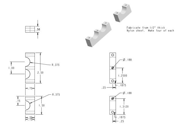
Cut four of these, place two of them end to end and drill the .188” holes all the way through. Use a bolt to clamp them together and then drill the large .75” hole. Be sure to use a drill press to insure the holes are perpendicular to the surfaces. Repeat the process for the four outer rudder pedal pivot blocks.
The two rudder pedal weldments are fabricated from .75” X .058” 4130 aircraft grade steel. Use the drawing as a guide.
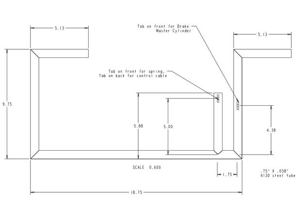
It is important to note that the tabs for the master cylinder are not welded in place at this time. They are welded after we have figuredout their best location, which is dependent upon the desired angle of the rudder pedal in its neutral position. We do not want the rudder pedal straight up and down as it is uncomfortable and will result in the brakes being applied when we are simply holding pressure on the rudder. Yet, we do not want the pedals tilted so far forward the brakes are difficult to apply. We will sit in the pilot seat and determine the optimal position (angle) for the rudder pedals then weld the tab into place.
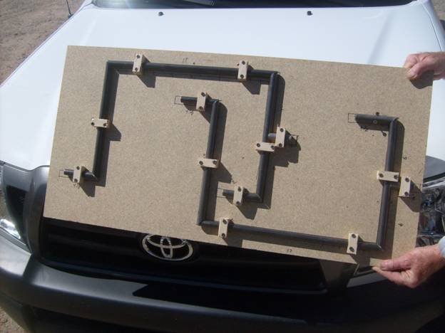
Example of using a board to hole the weldment in place for tack welding.
We will now install the hardpoints for the rudder pedal pivot points.
Mark a center line, front to back on the top of the heel rest. We will use this line as well as the forward edge as a reference for the placement of the rudder pedals. It is assumed that you have modeled your rudder pedal placement and have made adjustments to the dimensions given here.
Study the following pictures to understand the placement of the four nylon pivot blocks that will support the rudder pedal weldments. We will install four plywood harpoints where these pivot blocks will be installed.
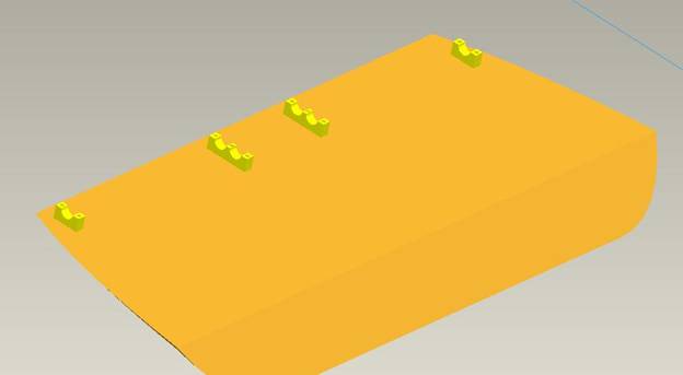
Four Pivot Blocks mounted to the heel rest
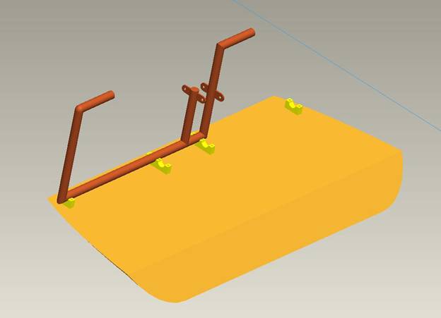
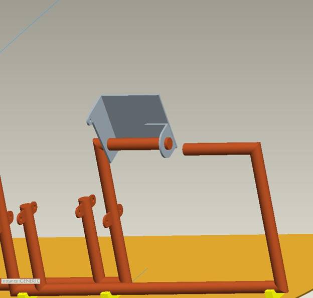
One welment installed
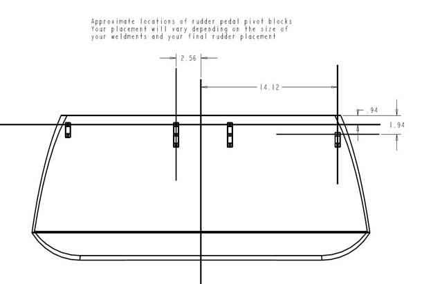
Below is a drawing of the approximate location of the pivot blocks. Test fit your pivot blocks to your weldments as the side to side location will depend upon the actual size of your weldments and may have to be adjusted as a result of your weld job. Besure to keep the bottom inside corners crisp as the pivot blocks rest against the upright sections of the weldment to keep them from moving side to side. If you have big radiused welds in the corners, the pivot blocks can not rest against the uprights.
Mark the location of the pivot blocks on the heel rest. Trim away the bottom glass in a section about 1” by 3.5” and remove the foam. Cut a ¼” plywood hardwood insert and micro in place. Layup 3 layers of BID on both sides of the hardpoints extending 2” beyond the the blocks on both sides of the heel rest over all four hard points.
Drill the holes through for the pivot blocks. Fabricate 10 K1000-3 bond in nut-plates and install on the bottom of the heel rest with the pivot blocks and welments in place insuring free movement.
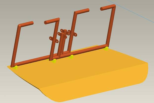
Second weldment in place
A attach bracket of 1/16” thick 4130 steel 1” wide is used to attach the rudder cables to the rudder pedals.
A pair of return springs are attached to the forward tabs and the firewall to keep the rudder cables taut.
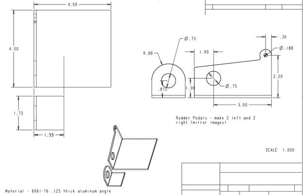
Rudder Pedals. The rudder pedals are fabricated from a section of 2.5” X 4” X 1/8” 6061T6 Aluminum angle – ACS 03-48675. Use the following drawing to fabricate two left and two right pedals. Don’t make four left pedals! The rudder pedals are fabricated from a section of 2.5” X 4” X 1/8” 6061T6 Aluminum angle. Print out the patterns and cut the pedals. Lightning holes may be added. The secondary angles are riveted into position with #30 rivets. Finally, the pedals are held in place with a section of .75” pvc sprinkler pipe attached to the rudder weldment with a single AN3 bolt drilled vertically through the weldment. Remember, the bolt goes through the top and the nut goes on the bottom. Always think, if the nut were to fall off, would the bolt remain in position?
The smaller part is then riveted on the back of the pedal as shown below. Use a section of ¾” tubing to help align it while drilling the rivet holes.
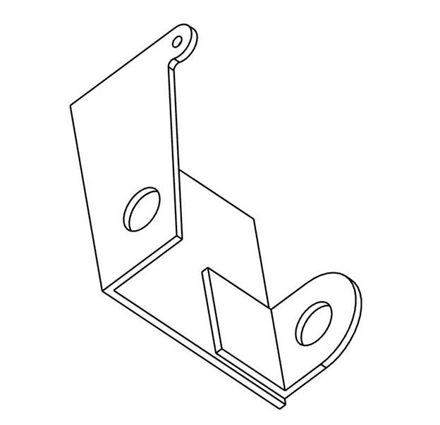
The pedal is held in place with a section of ¾” pvc water pipe and a single AN3 bolt through the rudder pedal weldment.
View of the back side of the rudder assembly showing pedal installation.
The short arms in the middle will attach to the rudder cables that run down the center of the aircraft.