Chapter 3 - Fuselage
Section 4 - Fuselage Features
Fabricating the Engine Mount Reinforcements
Engine Mounts – This section will describe the procedure to fabricate the reinforcement points at the firewall for the motor mount and the nose gear. We will be creating stout fiberglass mounting pads and angles that will transfer the load of the engine and the nose gear to the fuselage structure.
Step 1: Locate the position for the engine mount holes on the front side of the firewall. These pilot holes will just be used for reference at this point in time and will be drilled to full size later when we are actually ready to bolt up our engine mount. These holes will be covered up as we layup our fiberglass angles, we will drill them through once the glass is cured. Mark the holes on the forward side of the firewall, using the vertical and horizontal center lines all ready drawn there as reference. The lower two motor mount holes are located 10.25” inches to each side of the vertical centerline and 15.5” below the horizontal centerline. The top two motor mount holes are located 17” inches to each side of the vertical centerline and 1.5” below the horizontal centerline. Drill these holes with a ¼” drill bit.
Step 2: Use your nose gear mounting plate to locate the four holes through the firewall. I am assuming you are using the Dan Dielh KR2S nose gear. Drill the four nose gear mount holes like you did for the engine mount. The lower two gear mount holes are located xxx” inches to each side of the vertical centerline and yyy” below the horizontal centerline. The top two gear mount holes are also located xxx” inches to each side of the vertical centerline and yyy” below the horizontal centerline. Drill these holes with a ¼” drill bit.
Step 3: Place a shet of drop cloth plastic on your work table, and create a 2 layer UNI fiberglass layup measuring 24 inches by 5 inches. Let cure. We will cut triangular stiffeners from this stock creating the basis for our reinforcement points.
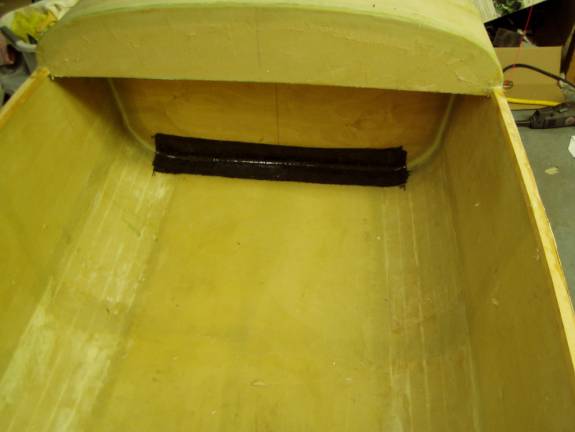
Step 4: Cut 8 strips of Carbon Fiber 27 inches long by 4 inches wide. Lay these up into the bottom corner where the fuselage meets the aft side of the firewall. Layup one layer at a time to insure you get good resin dispersal. You cannot see air bubbles trapped under multiple layers of carbon fiber, so take your time. The resulting angle will help transfer the landing loads carried by the nose gear and engine mount to the fuselage. Let cure.
Carbon Fiber Reinforcement for Nose Gear
Step 5: Print out the patterns for the reinforcement triangles. The Upper patterns are here and the Lower patterns are here. Using the pre-cured 2 layer laminate from the earlier step, cut four upper engine mount reinforcement triangles and 6 lower engine reinforce triangles. Use coarse sandpaper to roughen up both sides of all of these triangles.
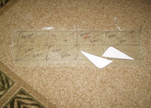
Trace the Triangle Patters onto Precured 2 layer Laminate Stock
Step 6: The aft side of the firewall should have the aircraft vertical centerline marked on it. Extend this line rearward for 6 inches or so. Then use this line to draw parallel lines on the fuselage bottom just aft of the firewall, 2.5 inches from center, 8.75 from center and 11.75 from center. Then draw vertical lines from each of these onto the firewall. Test fit the lower triangles to understand how much area around them must be cleaned in preparation for fiberglassing in the triangles. Use coarse sandpaper to roughen up the surfaces around the triangles and clean with acetone. If the lines are removed, redraw them.
Step 7:
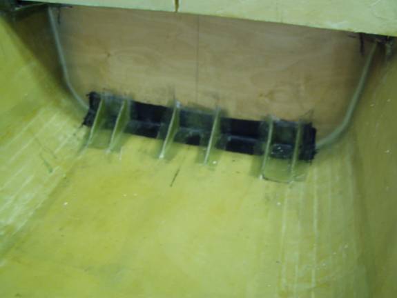
Step 8: Use CA (Super) glue to tack the triangles into place as shown in the following photo. Insure they are vertical.
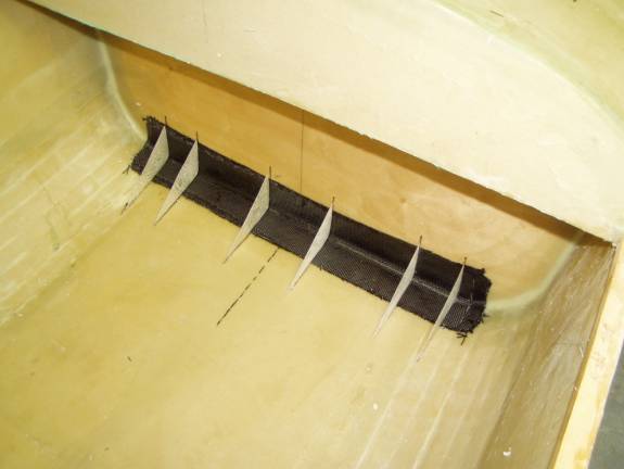
Lower Reinforcement Triangles Tacked into Place
Step 9: Now in a similar manner mark, prep and tack the four upper engine mount triangles into place. The first is placed between the firewall and the fuselage side immediately above the spruce stiffener. The triangle should have its shortest side against the firewall and the next shortest side against the fuselage mounted just on top of the spruce longeron. Another triangle is mounted likewise on the opposite side of the fuselage. The remaining two triangles are mounted 3 inches below the first two. Refer to the very last photo on this web page to get an idea of the final desired result.
Step 10: Mix up a batch of thick micro and create radiuses (about 3/8”) along both edges of all the triangles. Let cure. Sand.
Step 11: Print out the engine reinforcement layup patterns. These are found here:
- Nose gear reinforcement Center - 2 each
- Lower engine mount Center – 2 each
- Lower Engine mount and Gear mount outside – 4 each
- Upper engine mount top – 2 each
- Upper engine mount center – 2 each
- Upper engine mount bottom – 2 each
Step 12: We are now going to create 8 BID layups on both sides of each triangle. In the area between the triangles where the mounting bolts go through the firewall, there will end up being 24 layers of BID (the 8 layers folded in 3 times).
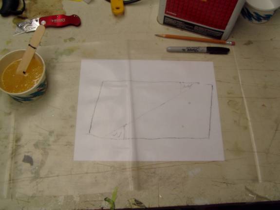
Patterns under Plastic
Step : On your work table, take a piece of paper and trace two patterns back to back as in the above photo. Then cover the drawing with a piece of plastic. This results in a near rectangular piece of fiberglass that will give you two completed layups. Cut a strip of fiberglass from your roll of BID the width of the shown rectangle, and then cut it into 4 rectangles for each completed layup.
The firewall reinforcement angles are some of the most challenging layups that you will be required to make. It is not that they are exceedingly difficult; it is just that the techniques used are unique and this task will end up taking much longer than you initially anticipate. Plan to take your time and do a few at a time. In the following example we will focus on the easier layup, the 4 lower-outside layups (Step 11-3 above).
Step : Create a four layer laminate on the plastic, over the pattern as seen in the following photo.
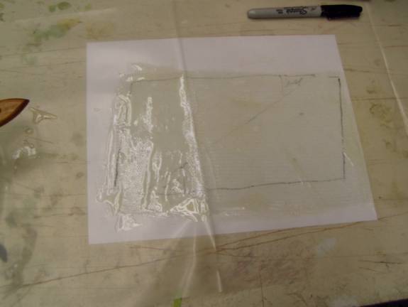
4 layer Laminates
When you have all four layers nice and wet, lay one of your patterns over the layup, and using fiberglass scissors, cut out required shape. Leave the paper pattern in place to stabilize the layup. Fold the layup on the fold lines.
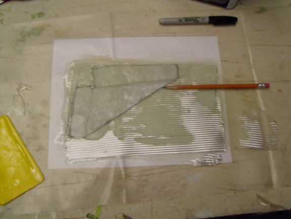
Paper Pattern
Wet out the side of the pre-cured laminate triangle, the firewall and the fuselage floor where the layup will lay, with your epoxy resin. You want a bit of excess resin on these layups to insure we work all of the air bubbles out.
Completed Lower Supports
Lay the layup into place, peel away the paper pattern, and carefully position it. Use a brush to stipple all the air bubbles out. This is a thicker layup and great care must be taken to remove all air from under the layup. Take your time and use plenty of resin, we will clean up the excess as our last step.
Once satisfied with the position of the layup, go back to your work table and either reusing the paper pattern or using a new one, cut out the second 4 layer laminate.
Install the second 4 layer layup over the first. Repeat the above step again being very aware that air bubbles are more difficult to see through four layers of glass. Leave the paper template in place to stabilize the stack until properly positioned. Remember, if the fiberglass layers wander and you seem to lose control of the layup—rip it out, throw it way, and start over. By the last layup this will seem easy.
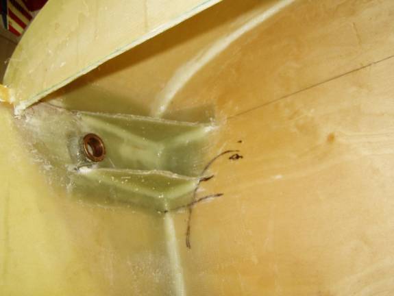
Completed Upper Supports
Repeat the process to complete all of the layups. The center layups are really no more difficult than the side layups. You just have to be careful when unfolding the layups on the center firewall section to get the three ends to overlay in an orderly fashion.
Let the glass cure. It is easiest to trim the edges when the epoxy is in the green cure state (about 8 hours of cure time). Then let fully cure and sand away any sharp edges.
Later, when the gear and engine mount is installed reinforcement plates will be floxed in against the firewall to interface with the washers and nuts.
Congratulations on completing a difficult task.