Chapter 8 - Finish the Wing
Section 4 - Fabricating the Main Gear
The gear is a trailing link design.
The upper gear leg has already been mounted into the wing. It was 24" long and will need to be cut down to 18". This assumes that you are happy with the "as designed" engine placement and prop clearance. If you are using a different engine with a different centerline or a different prop or want more or less ground clearance, it is the main gear leg length that adjusts ride height. Study the drawing below to get an understanding of the main gear configuration. The lower swing arms and spring supports are fabricated, be sure to make both a left and a right swing arm. The axel plate is on the outboard side of the gear leg on both sides of the aircraft. The right gear leg is shown below. The order of assembly is as follows:
- Fabricare a left and right swing arm
- Fabricate two spring supports
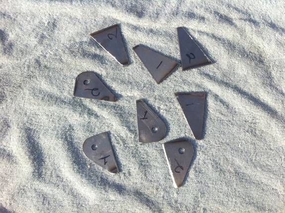
- Fabricate the four pivot plates
- Cut the main gear legs down to length (18" nominally)
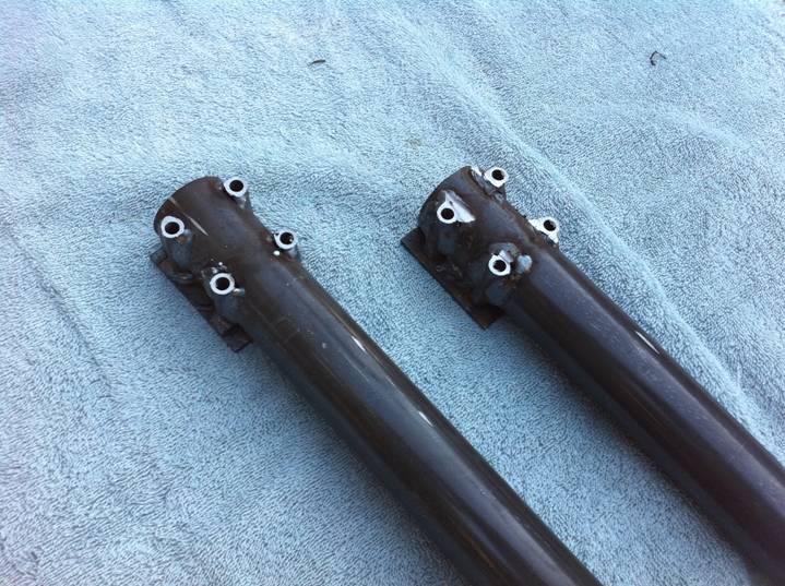
- Weld the upper gear tabs to the aft side of the main gear legs. Their position is measured from the bottom of the main gear leg.
- The pivot plates are used to fine tune the position of the swing arm.
Once the components have been fabricated the mounting position of the pivot plates are determines. The easiest way to do this is as follows:
- Mount the main gear leg back into the wing after cutting to length and welding the upper gear tabs into place.
- Position the two pivot plates at the bottom of the main gear leg. Clamp them into position.
- The initial position of the pivot plates is determined by leveling the aircraft and leveling a bolt that runs through the pivot holes in the pivot plates. This bolt should be parallel the ground. The pivot plates are clamped to the main gear leg and their position is determined as closely as possible and then a hole is drilled through the two pivot plates and the upper gear leg. The plates are bolted into placed. This is just the initial position, the pivot plates will be welded in place after their correct orentation is determined.
- Once the pivot plates are securely mounted to the upper gear leg, the rest of the gear leg assembly is put together, including the axel and a wheel with a brake disk.
- A laser level is clamped to the brake disk to insure that the wheel is tracking straight and that the brake disk is perfectly vertical with respect to the gorund. The position of the pivot plates is adjusted to insure these conditions. The holes mounting the pivot plates to the main gear leg can be adjusted to insure the swing arm is true to the aircraft. If the wheel tilts one way or the other, one of the pivot plates can be moved up or down with respect to the other. If the wheel does not track straight, the two pivot plates can be rotated on the main gear leg.
- Once the final position of the swing arm is determined, the upper gear leg is removed from the aircraft and the pivot plates are welded into place. The bolt is removed that held the pivot plates to the gear leg, and welded at the bolt holes.
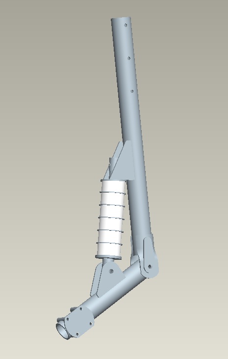
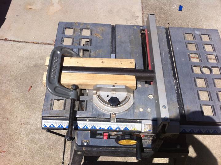
Table Saw with Metal Cut off Blade
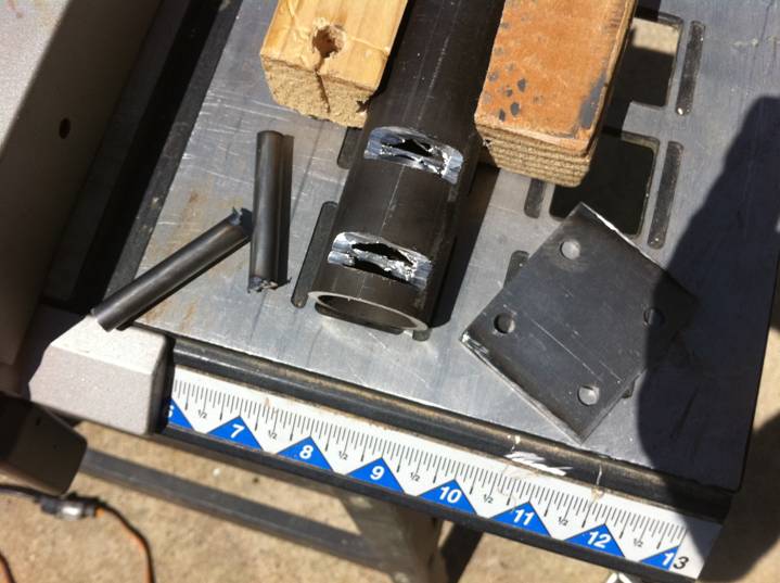
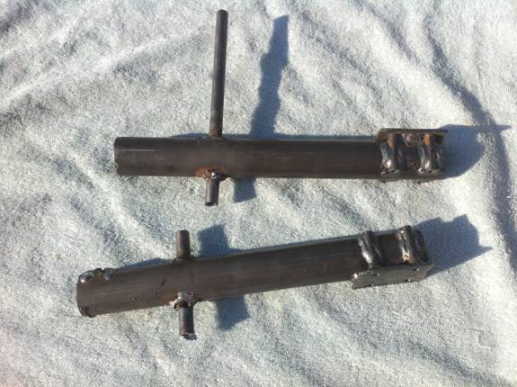
Notches cut in tube
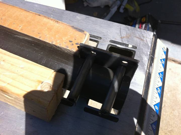
Test Fit
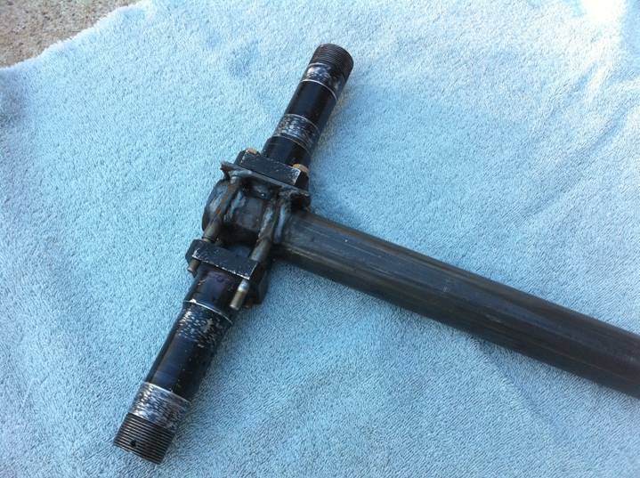
Axels used to fixture for Welding
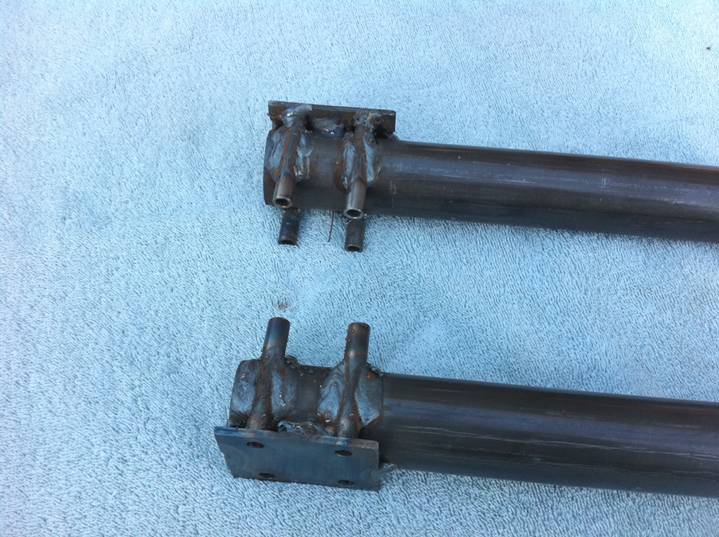
After Welding