Chapter 8 - Mounting the Wing to the Fuselage
Section 9 - Finishing the Fuselage
Wing attach to fuselage
Control Stick
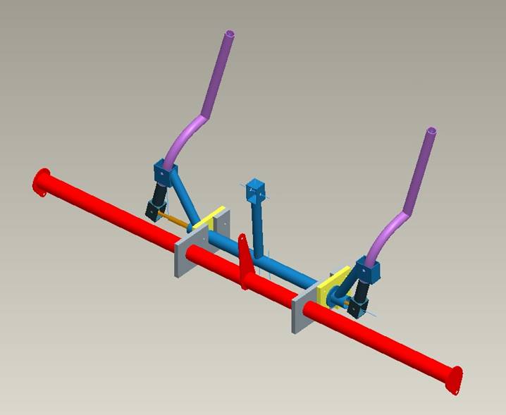
Complete Control Stick and Flap Mechanism
Fabrication of the control stick should be performed by a skilled welder. It is a crucial flight control element, a failure of which could be catastrophic. The control stick design of the Super2 uses a robust fabrication method and materials, resulting in a system that will end up being a bit heavier than probably necessary, but is strong and smooth operating. All moving parts use either brass or nylon bushings. The tubing is a little thicker than the stress analysis indicates is required, but thinner walled 4130 tubing is more difficult to weld.
Confirm that the stick position is a comfortable one in your seating location. The control stick as described here will be located, in its neutral position, centered above the spar tunnel, centered between the pilot’s legs, with the top of the control handle about an inch below the fuselage longerons. The control mixing mechanism needs to be in the specified location; however the shape of the control stick itself may be adjusted to relocate the control handle. The stick will move approximately 4 inches forward, backward and side to side as you cycle through the controls.
Start by obtaining the required material as called out on the following drawing:
1. Control Stick Mixer
2. Control Stick and Control Stick Sketch
3. Control Stick End
4. Control Stick Bushing A
5. Control Stick Bushing B
I first welded the stainless steel washers to the 1” tube using a V block as shown below. This insures the washer is square to the tubing. Remember to only weld on the outside of the washer as the inside is a bearing surface.
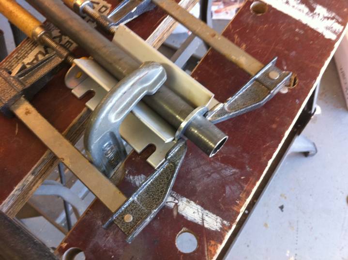
V block to square up Washer for welding
The control stick mixer components need to be accurately cut. I used a tubing notcher obtained from harbor freight for $35 to make clean joints between the round tubes. It takes a little patience, but the same effect can be obtained by a hack saw and grinding wheel. The control mixer needs to be jigged to insure the dimensions are true. Use a flat surface to secure the components while welding. Use an ⅛” aluminum spacer under the ¾” tubing to get it centered on the 1” tubing. Insure the distance between the washers is accurate and the distance between the .188” holes and the centerline of the 1” tube.. When welding, spot weld in several spots around the joint, That is don’t simply start at one point and weld all around the joint in one motion as this can cause the part to warp. Finally, we need to reinforce the joints where the three notched tubes attach to the large 1” tube. Cut 1” wide strips of 1/16” thick 4130 sheet, wrap them around the 1” tube and an inch or so onto the ¾” tubes. Tack weld the strips to the 1” tube, then use a propane torch to heat the strips and tap them with a hammer to conform to the shape of the smaller tubes. Finally weld all the way around the strips to reinforce the joints between the round tubes.
Next fabricate the nylon bearings. The large holes are critical and need to be cut using a quality hole saw. I used a flat blade wood bit and it worked fine. Once the 1” and 1.125” holes are drilled, the slots for the control mixer can be cut using a saber saw. Mark all of the bearings, left and right. We don’t want to get them mixed up later. Finally match drill the .188” holes in the left set and right set of bearings.
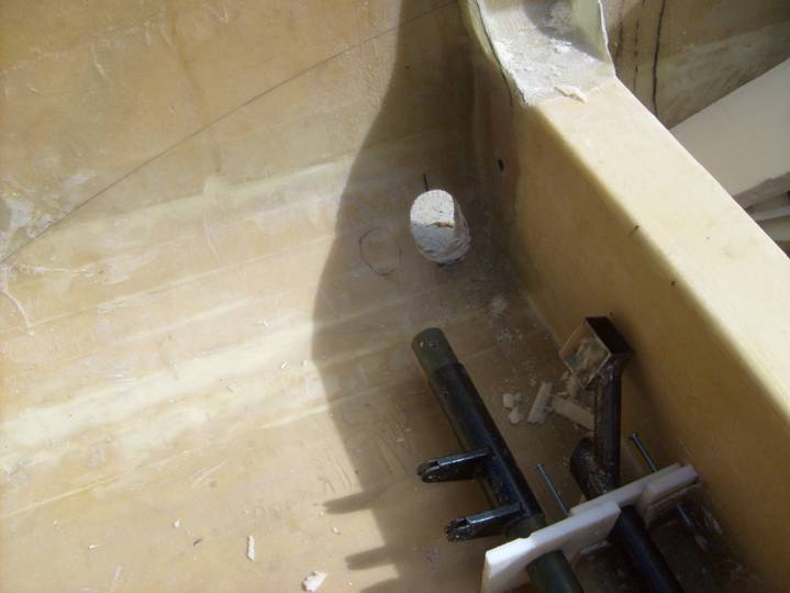
Once the control mixer and bearings are fabricated it is time to install them in the fuselage. The nylon bushings are installed as shown below with the larger bearings inboard. The notches in the corners of the bearings are located in the corner where the spar tunnel meets the fuselage floor. Take two pieces of two layer, procured BID fiberglass and cut them the same size as the smaller of the two bearings. Install the control mixer into the bearings. Match drill the procured laminate and screw them to the inboard side of the bearings. Now place the whole assembly into the airplane on the aft side of the spar tunnel as shown below. Unlike the photo below, the 1.125” flap tube also needs to be installed between the two bearings for the bonding operations to insure proper alignment.
Installation of Control Mixer Torque tube
Center the mixer assembly left to right and insure it is square to the floor and spar tunnel. Then use a mixture of 5 minute epoxy and flox to create a bead around the inboard side of the two layer laminate, the spar tunnel and the fuselage floor. Once cured, very carefully--so as not to disturb the position of the procured laminate--remove the bearings and control mixer assembly. Layup an 8 layer BID and bond to the inboard side of the two layer laminate. 4 layers should extend 2 inches onto the fuselage, 2 layers should extend 3” and 2 layer should extend 4”. Let this cure, then trim and drill using the holes in the procured laminate as a guide. Reinstall the control mixer assembly and verify smooth operation of the control mixer and flap tube.
Project the flap tube and control mixer main tube onto the fuselage side walls as shown below, and cut holes in the side of the fuselage as shown. These can be trimmed to size later when the actual control push/pull tubes are installed. The aileron push/pull tubes will pass through the sides of the fuselage without touching, and the flap tubes will pass through the fuselage side with a bearing.
Project tubing through fuselage side
The control stick is fabricated from ¾” X .035” 4130 steel tubing. To create the bent section, I filled the tubing with sand and used a conduit bender purchased from Lowes Hardware. I made a 1:1 drawing as a template, and welded the straight section at a dual angle cut. This joint is reinforced with sections of 1/16” flat steel plate on each side and welded into place. Notice that the two straight sections of the control stick are not parallel to each other, there is an offset angle of 3 degrees. Finally use a V block and drill the hole for the bearing support. A small brass tube is installed inside this bearing support and tightly screwed to the control mixer.
 .
.
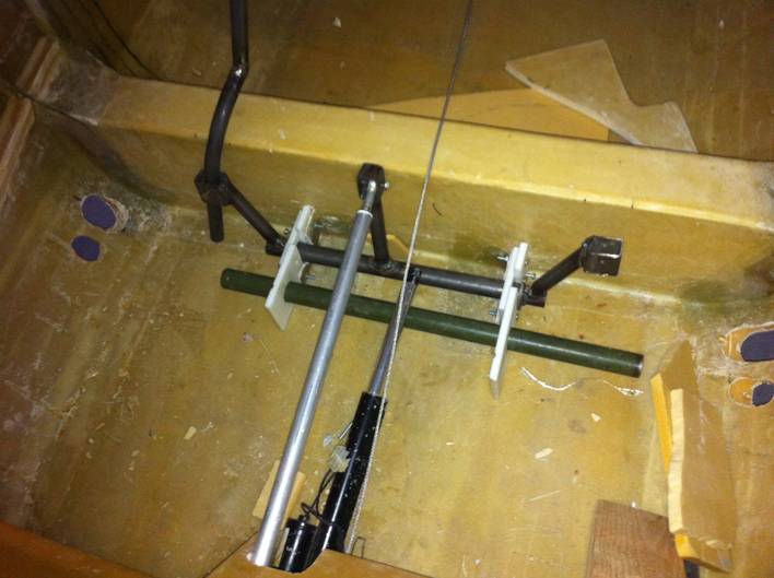
Completed Control Stick Mixer Installation
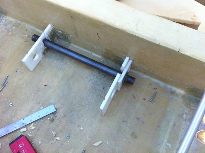
A pushrod passes through the middle of the 1” control mixer and ties the two control sticks together. It is fabricated from an 18” section of 3/8” X .048” 4130 steel tubing. It is tapped at both ends to accept the 5/16-24 end of a GMM-3M-570 Aurora bearing. The two bearings have a 5/16” lock nut (unlike the photo below) jammed against the steel tube once the proper length is adjusted. The tube should allow the two control sticks to be vertical at center stick position.
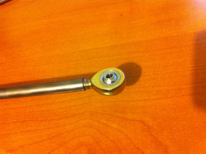
Control Stick Pushrod
The control stick ends are fabricated as shown in the drawing found at the top of this page. The installation of these is critical for proper control mixer operation. The push/pull tubes running out to the wings are attached to the control stick ends with the pushrod running through the middle of the control mixer tube. The pushrod is mounted against the inside of the control stick end and the rodend mounted at the end of the aileron push/pull tube is mounted with a washer on each side. These washers are important as they give the rod end bearings room to rotate as the elevator is operated. This will be discussed further when the wings are installed. For now, install the pushrod inside the square tube of the control stick end, mounted against the wall with a 5/8” spacer. With the entire control mixer assembly together, adjust the up/down position of the control stick ends so the pushrod does not contact the inside of the control stick mixer throughout its movement side to side. Then drill two .188” holes 90 degrees to each other through the control stick and the control stick ends. Install AN3 hardware to secure the control stick ends to the control sticks.
Finally, the elevator pushrod is installed from the control mixer to the lower side of the elevator idler at the back of the control tunnel. The final assembly of the control system is performed after the wing is attached to the fuselage.
The next section discusses the installation of the flap control mechanism.