
Design Analysis Home
This page captures the design intent and the design analysis performed on the Super2. This aircraft is still under construction so has not been flight test, therefore all of the data supplied here is theoretical.
Design Analysis Table of Contents
- Genesis of the all Composite KR
- Design Goals
- Modifications to KR2S
- Why Composite?
- Overall Aircraft Sizing
Genesis of the all Composite KR
Defining the Mission –
What were my goals in building a homebuilt plane? How did they lead me to an all composite version of the KR? They were many and some were mutually exclusive. I wanted the following out of an airplane:
- Economy – closer to 5 gph than 10
- Inexpensive to build, closer to $15,000 than $150,000
- Safe Airplane
- 2 seater with side by side seating
- low wing
- Quick, in excess of the SLA limit
- forgiving handling qualities
- fun to fly
- not to difficult to land
- Usable load to include two adults and a little luggage
- A plane I could build myself
- Good taxing qualities
- Simple
- Reliable
- Take advantage of the latest technologies and methods
- Able to go cross country, but fun to fly locally.
- A plans built plane – I want to build as much of it as I can, even the engine.
After reviewing the offerings I settled on the Rand-Robinson KR2S. It is simple, inexpensive to build and operate and the specifications touted by Rand-Robinson indicated it would meet my requirements. The second reason I settled on the design was the KR community; there are many active builders and even more active examples flying with well-documented characteristics and capabilities.
I ordered the plans and committed myself to the KR2S. Upon receiving them and continuing my research I realized that the design was quite dated and in fact could not meet all its specifications, at least a single example could not meet them all at the same time. Plus, I am a tall guy and I really would not comfortably fit in the cockpit with a passenger and a bit of baggage. No worries, many people have wrestled with these same issues and have dealt with them. I would follow in their footsteps and modify the KR2S design. I settled on the following modifications:
- Use the KR-2S as the starting point
2.) Powerplant - 2700cc Corvair
3.) Use a front starter on engine
4.) Tri-gear
5.) new KR airfoils for wing, vertical and horizontal stabilizors.
6.) new Angle of attack for main wing
7.) new horizontal stab incidence
8.) Increase area of horizontal stab, but not elevator.
9.) Slightly larger rudder, extends in front of hinge line above vert. Stab. (counter weight here).
10.) Balanced control surfaces - both aerodynamic and static
12.) move firewall forward
13.) move tail back
14.) widening the fuselage at top even with shoulders
15.) move widest fuselage point to coincide with shoulders
16.) Canopy raised 2”
19.) Small windows in the turtle deck
20.) Dual Center sticks
22.) Dual rudder pedals mounted to floor
23.) Pilot only brakes on the rudder pedals
24.) Standard Rudder control cables routed down center instead of sides
26.) wing tanks – small header tank
27.) Slightly longer wings, washout at tips, small winglets
28.) Slotted Flaps
29.) Redesign the fuselage top longeron placement to result in a flat top boat, coplanar with the aircraft's horizontal datum plane.
30.) 30 gallon fuel - 3 gal header, 13.5 each outboard wing.
32.) cable to bellcrank aileron control
33.) Bent spar - constant dihedral wing from fuse side to wing tips.
Given these modifications I laid out the new fuselage as shown below:
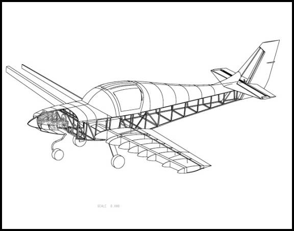
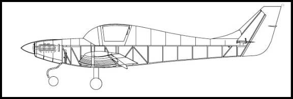
Some performance characteristics of the KR2S that have been addressed
by lengthening the fuselage and increasing the size of the horizontal
stabilizer include pitch sensitivity, small allowable CG range
Horizontal Tail Sizing
A measure of the tail effectiveness is the horizontal tail volume coefficient:
A well-behaved aircraft typically has a value which falls in the range:
0.30 ... 0.60. If the value is too small, the aircraft’s pitch
behavior will be very sensitive to the CG location. It will also show
poor tendency to resist gusts or other upsets, and generally “wander” in
pitch attitude, making precise pitch control difficult. Notice that the
KR2S is at the low side where as the KR2-VX is in the middle of the range.
It is an interesting exercise to calculate the value for comparable aircraft.
The KR2S has the smallest Horizontal Tail Volume Coefficient of all of
the kit planes I looked at in its class.
The horizontal tail volume coefficient also directly affects the allowable
CG location. The derivation of the formula is beyond the scope here,
but it is straightforward to evaluate for any aircraft configuration.
The KR2-VX has an allowable CG range double that of the KR2S.
Vertical Tail Sizing
The primary role of the vertical tail is to provide yaw damping, which
is the tendency of yaw oscillations of the aircraft to subside. The vertical
tail also provides yaw stability, although this will be almost certainly
ensured if the yaw damping is sufficient. One measure of the vertical
tail’s effectiveness is the vertical tail volume coefficient: Most
well behaved aircraft typically have a value which falls in the range:
0.02 ... 0.05. If this value is too small, the aircraft will tend to
oscillate or “wallow” in yaw as the pilot gives rudder or
aileron inputs. This oscillation is called Dutch Roll, and makes precise
directional control difficult. The KR2S vertical tail size and moment
is within the acceptable range, however the vertical tail was increase
somewhat on the KR2-VX.
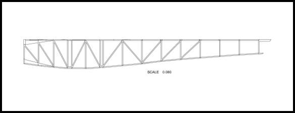
When running a series of analysis on the truss box fuselage it was found
that there were some issues including tortional rigidity of the rear
fuse. These were addressed by: 1.) Additional trussing in the
rear portion of the fuselage. 2.) Triangular solid members where the
sides meet the firewall. 3.) Additional shear web mounted on top of the
fuselage half way between seat and the tail.
One assumption I have made is that the turtle deck does not add any structural
strength to the fuselage. Depending on the method of attachment, the
turtle deck does add some stiffening toward the tail end.
The triangular blocks at the top and bottom where the fuse meets the
firewall are intended to help transmit the load of the engine mount to
the fuselage. there will be angles bolting behind the firewall tying
the engine mount into these triangular blocks.
Currently the design calls for a small shear web across the top of the
fuselage just behind the seat. I have added a second one halfway back
between this one and the tail. An important point to make here: The seat
back is an important structural bulkhead in the fuselage. It should be
solidly tied to both fuselage sides. I have seen aircraft where the seat
back is hinged forward--this would be fine as long as when the seat is
in its back and locked position, it is securely tied to the fuse sides.
At this point I was quite happy with the design and believe it to be
as good as any KR flying. The additional weight was minimal and
the strength and tort ional rigidity of the rear fuse were sufficient
to handle the increased moment arm and increased size of the horizontal
tail.
How did we get to Composite?
A friend of mine, Zeke Smith, talked me into building my wings from
the ‘outside in’ using a female wing skin mold, then building
all the wing internals on this wing skin. This is a technique that he
espouses in his latest book “Advanced Composite Techniques”. As
I was won over to the idea of attempting this, I got to thinking, why
not go all composite? I already had the wooden truss box fuse model
in the computer so I ran a comparative analysis of that design against
one with a composite construction. The structural analysis shows that
the composite fuselage has superior strength to weight. It is actually
not that much lighter, but stronger and stiffer given my longer fuselage.
The analysis shows that the wooden structure is plenty strong, but has
a much more uneven stress distributions.
This is something that Ken Rand wanted to do at some point, create an
all-composite version of his plane.
So using techniques from Zeke’s books, I designed a composite KR
fuselage and tail feathers. The fuselage is easy to build using
1/2" last-a-foam. The panels are fabricated on the floor or work
bench so little glassing is required bending over into the fuselage. The
foam panels are only bent in one axis. The fuse sides are laid at the
KR 82 degree angle and curved in, and the rear sides of the fuse twist
from the 82 degrees to vertical at the tail. The front deck and turtle
deck are made the same way as the current KR. One difference is that
I am glassing the fuse and turtle deck together as I am using the whole
rear fuse "tube" as a structural member. I am rounding the
bottom corners of the fuselage as has been done on a few KRs.
The technique I am going to use has you glass the outside of the last-a-foam
first, then a large piece of flat MDF or melanine coated with mold release
is laid on top while the glass cures. This gives a nice smooth surface
that is finished easier. Then the piece is cut to shape as defined by
the CAD model and bent into the proper shape. A form is used to hold
the fuse in position while the inside is glassed. Bulkheads are added
and there you go....a boat.
Once I decided to build an all-composite airplane I stepped back and did a top down design analysis of the aircraft. Following are the major steps of that analysis.