Chapter 5 - Gull Wing Canopy
There are many ways to mount the canopy on the aircraft. Securing the one-piece canopy to a fiberglass frame and then hinging the complete assembly is the traditional method and would work fine on the Super2. It could be hinged forward or to the side. However, I have always been a big fan of gull wing doors and have chosen to build this style. I enjoy being able to taxi with my doors open. The Gull Wing canopy is more work and is a bit heavier. If executed as shown here it will be easier to get a reliable and repeatable seal.
Section 1 - Canopy Outer Skin
I will present two methods for building the Gull Wing Doors. The first method is simpler, but will require more prep work to achieve the same level of finish on the final product. The second method uses a poor man’s vacuum bagging technique. This simple vacuum bagging technique works well with the small parts involved (about 1 foot by 3 feet on average). I recommend using vacuum, but understand that this brings another level of complexity and cost to the building process. Refer to my construction methods section on Poor Man’s Vacuum Bagging for a description of the compromises I make to reduce the cost and complexity of traditional vacuum bagging. By vacuum bagging we obtain a very smooth finish on the outside of the canopy frame, the lightest weight parts and nice looking surfaces on the inside.
The following canopy installation assumes that the canopy is purchased from Todd’s Canopies and is the one tooled for the Super2. The canopy is a little larger than the typical Dragonfly canopy used by most KR2S builders and has the proper curves to match the fuselage sides and front deck. If a standard Dragonfly canopy is used the following methodology should work fine, but the measurements stated here and the provided drawings would have to be modified to match the specific canopy. In any case, it remains important to sit in the fuselage with the canopy in place to insure the measurements and positioning of the windshield frame are correct.
Overview
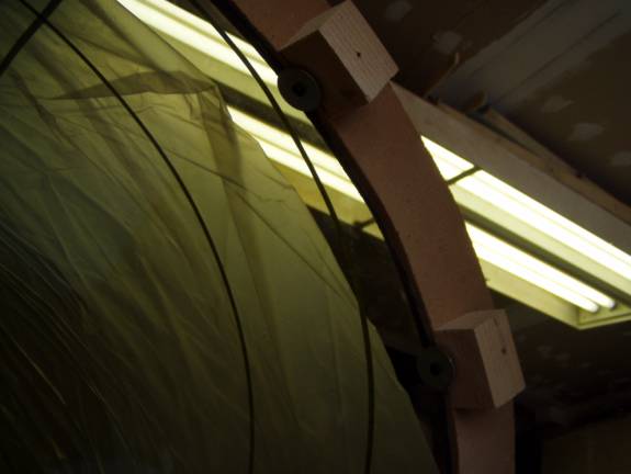
The canopy is quite elastic and floppy before it is mounted in a frame. Because of this, a wooden support structure is built to stabilize the Plexiglas and hold it in its proper location with respect to the fuselage. This wood support structure and the canopy are built resting on the fuselage. Measurements are taken and the location of the canopy roof, windshield frame and rear canopy post are located. These are marked on the canopy with painter’s pin striping tape. Regular masking tape should be avoided around Plexiglas as it leaves a nasty residue that can be difficult to clean off later. The builder will sit in the aircraft to double check the visibility and head clearance of the suggested frame location. Once satisfied with the locations of the canopy frame, the canopy is used as a mold to make the frame parts. The wooden canopy support structure and canopy are removed from the fuselage, and turned upside down. Using the poor man's vacuum baging techniques, parts are made using the inside canopy surface as a mold. If one does not want to use vacuum, the parts can be fabricated by simply using a squeege to form the layups to the shape of the inside canopy. Canopy doorframes, Fuselage door frames and the windshield bow are fabricated in pieces in this manner. These pieces are then bonded together to form the outside skin of the frame. Then foam is added and the inside is covered in carbon fiber cloth and resin to create a sandwich. A very stiff, strong and light weight frame results. The canopy door frames are cut out of this frame. The frame has features along the edges to engage a rubber bulb weather stripping creating an air tight seal. Hinges are added to the top and a latching and locking mechanism is added at the bottom to secure the doors to the fuselage. Finally the Plexiglas is cut down and installed into the frames.
Materials Required:
- 3 each 8 foot 2X4 studs
- 3" sheet rock screws
- 2" sheet rock screws
- shoulder washers
- 4 each eybotls
- MDF - section left from the sheet used to create fuselage formers
Step 1 – Building the Wooden Canopy Support Structure
Take two 2X4s and cut them in half to create four lengths about 48 inches long. Place two of these across the fuselage—one just behind the seat and the other a couple of feet behind the firewall. Look forward a few photos to get an idea of the desired support structure. Place the two other cut down 2X4s across the first two right at the fuselage side wall. Secure them with sheet rock screws.
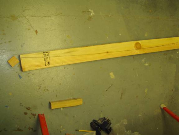
Fuselage edge marked on 2X4
Step 2: Mark the fuselage sides on frame. Now, flip the whole structure up side down so the side to side members are in the same location, but the left side 2X4 is now resting on top of the right fuselage side and the left side 2X4 is resting on top of the right fuselage side. Adjust the position of the 2X4 located right behind the seat back so the forward to backwards positioning of the structure is the same as if it were in the proper orientation. Split the distance the 2X4s over hanging the fuselage sides equally side to side. Use a sharpie to trace the fuselage side curve to the side 2X4 frame members. Flip the structure back over, line the sharpie marking with the outside of the fuselage by sighting straight down and you have located the position of the canopy side to side.
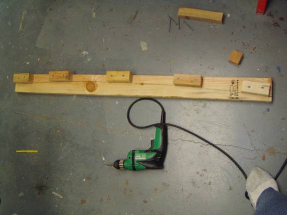
Attaching support Blocks along canopy outline
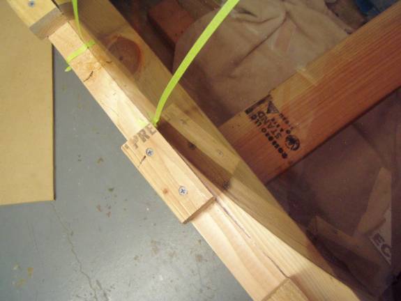
Step 3: Attach support bolcks: Take the remaining 2X4 stud and rip it down to 2X2. then use sections of this 2X2 cut in 3 or 4 inch lengths to create small wooden blocks. Attach the wooden blocks aligned with the sharpie line you made to define the fuselage wall.
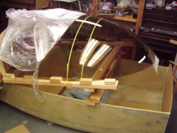
Canopy held in position with top of Fuselage
Step 4: Set the canopy into the support frame. The canopy will be aligned with this line as seen in the above photo. The canopy is rested on these last two 2X4s and positioned so that the front of the canopy is about 7 inches from the firewall and the back of the canopy is just at or back of the top of the seat back. This is just an initial starting position. The highest point of the canopy should be directly over the seat. This is where your head will be. Place a builders level running front to back, balanced on the top center of the canopy. If the fuselage is level and the level is level, its position will indicate the highest point of the canopy. This point should be directly over the middle of where your butt sits. Move the canopy forward or rear ward to obtain this position. Place a piece of tape on the canopy and mark the location on the wooden support structure.
A view of the point where the canopy moves inward
Step 5: Position the Canopy in the support frame. At about 32 inches behind the firewall the canopy will begin its curve inward away from the fuselage sides. Using these guidlines and sitting the in the aircraft obtain a canopy position you are satisfied with. Mark the canopy, support frame and fuselage to record the desired canopy location.
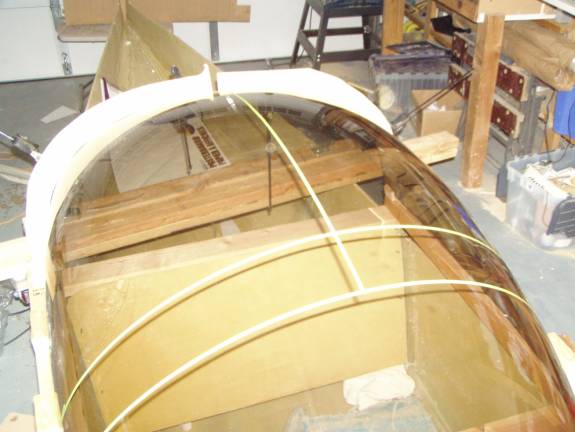
Canopy sitting on Wooden Support Structure
Step 6: Support rear of canopy. Next we will make an simple support structure for the rear edge of the canopy. A piece of ½” MDF is used. Take a large sheet of cardboard and lay it against the back of the canopy just rear of the seat back. Trace the shape of the canopy onto the cardboard. Carefully study the shape of the curve you have traced. In my case the curve was not symmetrical and I had to redraw it so the two sides of the canopy had the same shape. Use a razor knife and cut out the resulting curve and use the cardboard piece as a template to trace the curve to a piece of ½” MDF. Make two identical sides. Lay the two bows on top of the canopy. I used clamps to secure the MDF support pieces to the rear of the canopy frame to test their fit.
Step 7: Marking the Frame Outline. The canopy should be very secure and stable at this point. It is now time to mark the location of the canopy frame onto the canopy. The laser level is an invaluable tool for this task.
Lazing the windsheild bow location
The windshield bow will eventually be about 5 inches wide, 2 inches of windshield bow and 3 inches of canopy doorframe. The windshield bow tilts forward at 10 degrees and intersect the top of our wooden structure 32 inches behind the firewall. Mark this location on both sides of the canopy with small pieces of masking tape. Block up the front of the canopy on its frame so the edge creates a 10 degree angle. Position the laser level with a vertical line so it intercepts the two pieces of tape and extending up on the canopy. This line defines the front edge of the windshield canopy bow. Use the painter pin striping tape to mark the location of the laser line.
Step 8: Mark the location of the backside of the windhsheild bow.
Move the laser level 5 inches rearward and again mark the rear edge
of the windshield bow.
Marking the backside of the windsheild bow
Step8: Marking the canopy frame centerline. The canopy roof is aligned straight down the aircraft centerline. Mark a center line with the laser level aligning the vertical line on the firewall and a point at the tail.
Marking the canopy centerline
I was able to paint the vertical line on my firewall, a line on the seat back, and the line down the center of my rear fuselage with the laser. Mark this line with the painters trim stripe tape down the center of the canopy as shown above.

Step 9: Using the same technique with the laser level, blocking up the rear of the canopy structure and painters masking tape, mark the rear canopy structure. The rear canopy frame should be tilted rearward at 30 degrees and should roughly line up with the seat back at the rear side and 7 inches in front of the seat back on the front side.
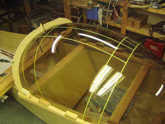
All canopy outlines complete
Step 10: Mark parallel lines 7 inches of the centerline down the middle of the canopy. The final roof section will be 12 5/8” wide. Mark a 3 inch radius fillet where the canopy frame roof meets the windshield bow and the rear canopy frame post. Climb into the aircraft a final time and confirm that the location of the canopy frame is optimal
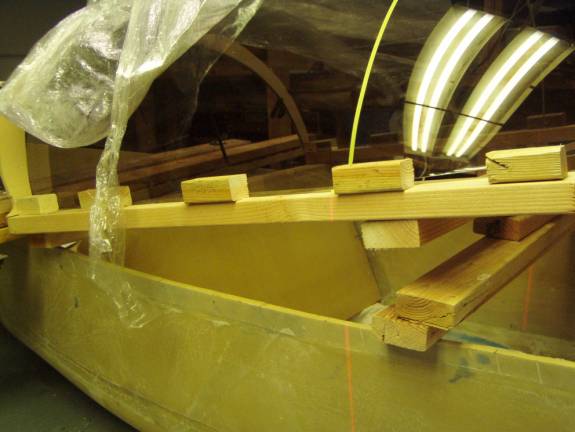
Step 11: Secure the rear of the canopy to the supoort frame. Refer to the follwoing photograghs. Add 8 2X2 blocks to the rear MDF support bow with 2 inch sheet rock screws right at the curved edge. Then add a single screw and shoulder washer to the block so the shoulder swasher will overhang the plexiglass. these washer will hold the canopy to the bow to insure it holds its shape when we invert the whole structure.
Suppoprt Blocks
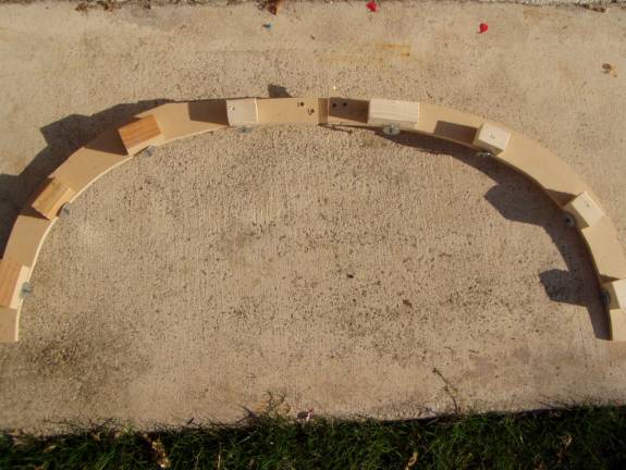
Suppoprt Blocks
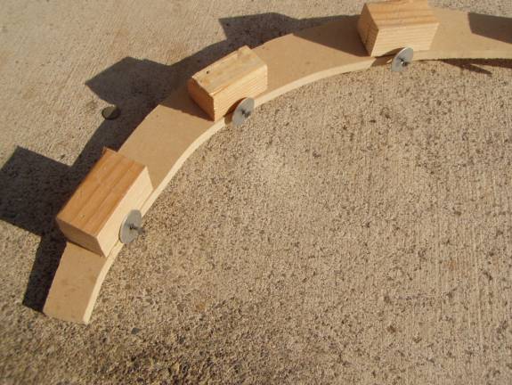
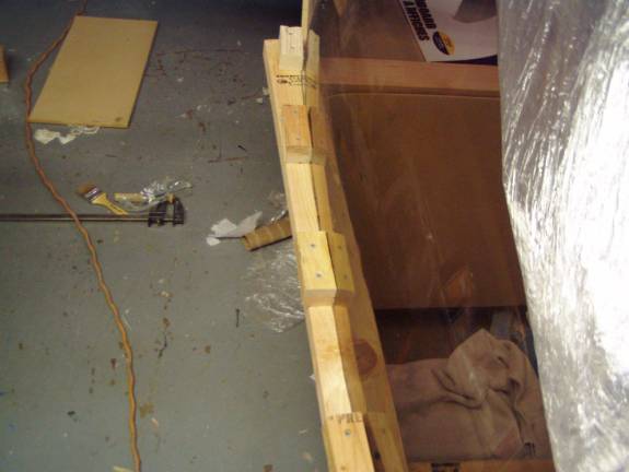
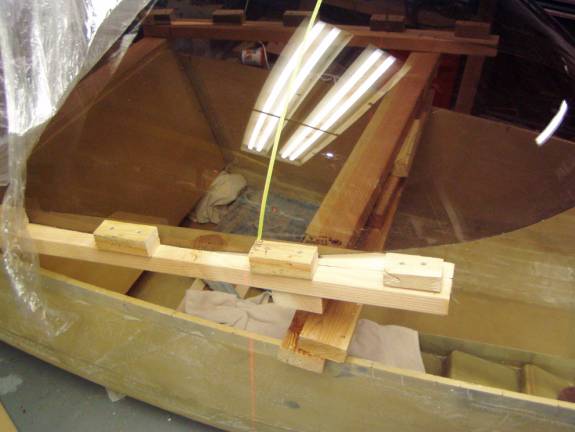
Closeup of shoulder washers
Closeup of rear support bow installed on support frame
Notice how the shoulder washer are used to hold the canopy against the support frame.
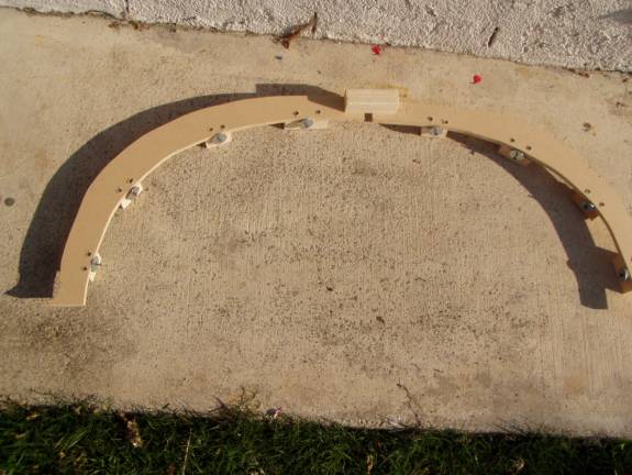
Step 12: build the forward support bow. You can not simply trace the cross sectional shape of the canopy as you did with the rear bow. Use a piece of coat hanger or other soft material that can be bent to the shape of the canopy. I used a length of ¼” aluminum tubing. It can be easily bent and holds its shape very nicely. Bend the tubing to the proper shape and transfer the shape to a piece of MDF as was done for the rear wooden bow.
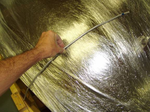
Determining shape of forward support bow
Again make sure that the two sides are symmetrical. Cut the MDF bows out using a saber saw and staple terry cloth to the inside radius as was done earlier. Again use short sections of 2X2s to secure the wooden bows to each other and to the 2X4 side rails of the canopy structure.
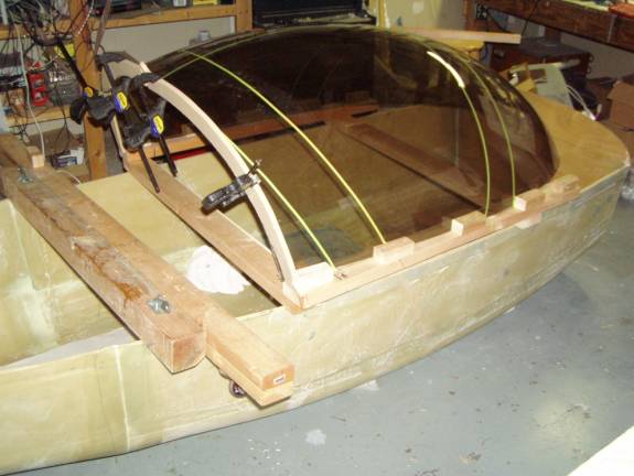
Step 13. Secure the canopy to the support frame. Screw in four eye bolts into the structure and run straps or nylon ropes across the top of the canopy to secure it in position for when the structure is inverted. Remember to use a terry cloth towel to protct the canopy from chaffing against the straps.
Step 14: Build the support frame legs. Take another 2X4 and cut it into four equal lengths of about 24”. Take a second length of 2X2 and cut it into two lengths of 48”. The 2X4s will become legs and the long 2X2s will be leg supports. Screw the 2X2 to two of the @x4 legs and then attach the assembly to the canopy structure side. Repeat for the other side. Screw a single 2X2 across the frame to secure the two leg halves.
Step 14: Remove the canopy frame, the canopy along with it, from the fuselage and set, upside down, on your work surface.