Rear Fuselage Fabrication
The rear section of the lower fuselage is created with 6 pieces of foam,
four of which are ½” thick and two of which are ¼” thick.
Print out the drawings for the following parts: Rear Fuselage Side, Rear
Fuselage Corners, Rear Fuselage Bottom and the Rear Fuselage Layout.
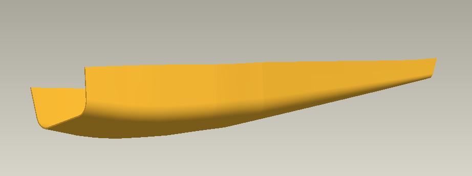
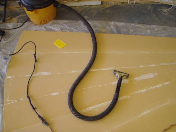
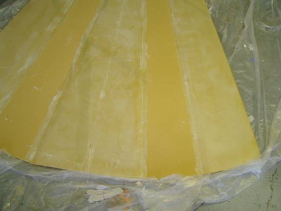
Refer to the following photo to get a feeling for the layout of the tail
cone. The bottom and sides are made from ½” foam and
the radiused section is ¼” foam. The ¼” foam,
when glassed on one side, bends very nicely.
The order of assembly for the tail cone panel is as follows:
- cut out the 6 last-a-foam panels. There will be two identical rear fuselage sides cut out of ½” foam, two identical rear fuselage bottoms cut out of ½” last-a-foam and two identical rear fuselage corner sections cut from ¼” last-a-foam.
- The six pieces of last-a-foam are bonded to one another to form a flattened cone shape.
- The ½” foam is beveled where it meets the ¼” foam.
- This exposed side will become the inside of the fuselage. The ½” foam is covered with a single layer of BID down to and including one inch of the ¼” foam. The uncovered ¼” foam will become the inside radius of the corners.
- The aft end of the ¼” foam has slots cut into it to facilitate the tight radius bend.
- The entire panel is flipped over. There are ¼” foam blocks placed under the ¼” foam so the top is completely flat.
- The outside of the panel is covered in a single layer of BID in two operations. Our sheet of MDF is used to give us a tooled surface finish.
- The panel is set a side while we build the forward fuselage section
- The completed panel is laid across the form and bonded to our already completed forward fuselage.
- The form is flipped over and the ¼” foam is now glassed on the inside.
- The bulkheads are installed and the former are removed.
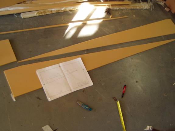
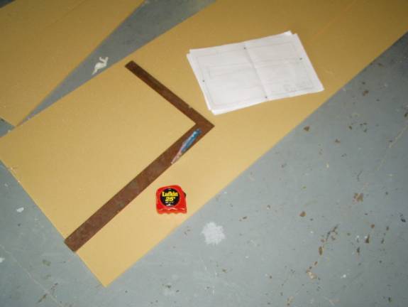
Cutting Out Two Fuselage Bottoms
The Fuselage bottoms are cut out of a single rectangular piece of foam
as shown above to minimize the amount of foam needed.
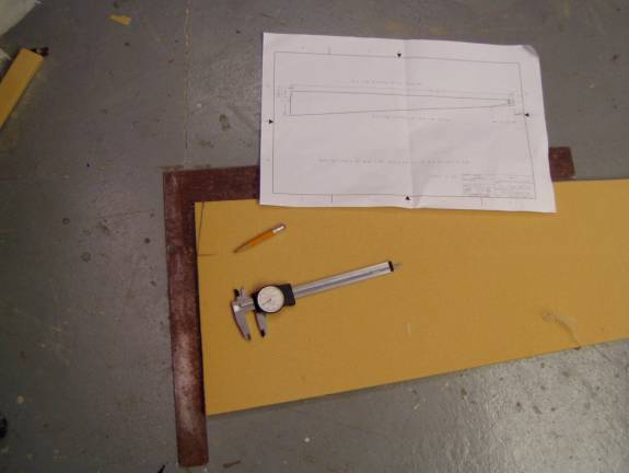
Proper Positioning of the Fuselage Bottom Pieces
The two rear fuselage bottom pieces will be positioned as shown in the
above photo. Cut out the two radiused sections from ¼” last-a-foam.
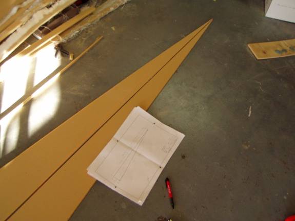
Cutting the Radiused Sections
Finally cut the rear fuselage sides from ½” last-a-foam.
Cutting the Rear Fuselage Sides
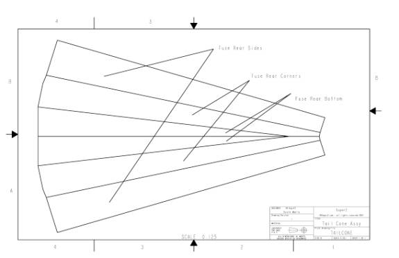
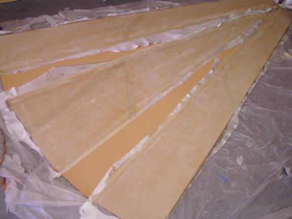
Once all of the foam pieces are cut lay them out on a large drop cloth
and position them as in the layout diagram. None of the parts are symmetrical,
so pay close attentions as to the orientation of each part and how it
fits with its neighbors.
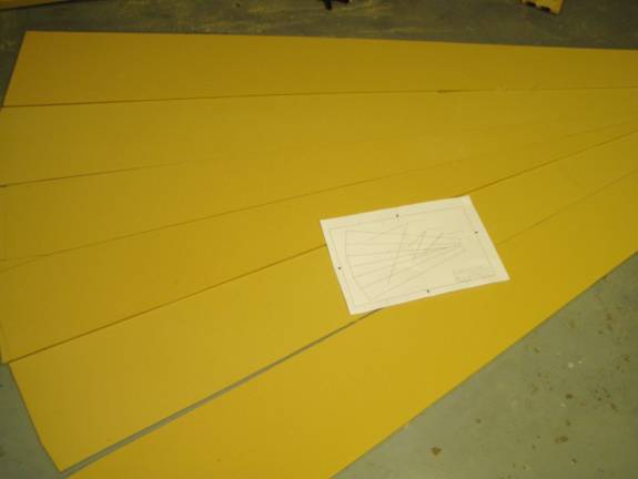
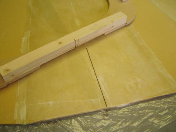
Proper positioning of the rear fuselage panels
Once you are satisfied that you have the panels oriented properly, pull together some 1” X 2” scrap ½” thick last-a-foam blocks. These blocks used in conjunction with finishing nails are used to hold the panels together while the micro cures.
Mix up a good sized batch of thick micro and butter up the edges of
the panels. Do not over do it. Just coat each side well and
remove all excess. You do not want the micro oozing out the bottom
and spreading onto the panel surfaces. However you do not want gaps between
the foam panels, either. If there are gaps, carefully fill them
with micro. Use the small block and finishing nails to secure the panels
while the micro cures.
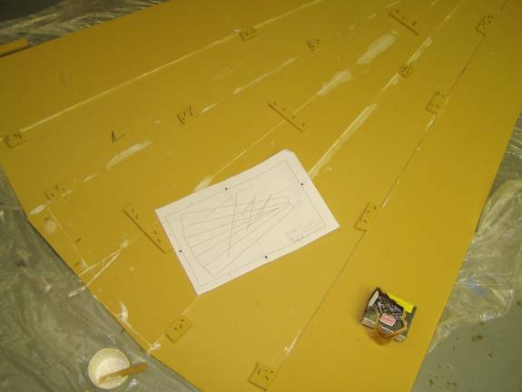
Scraps of foam used with nails to secure panels
After the micro has cured, remove the temp blocks and inspect the panels. You may need to sand the micro flat in a few places and you may need to repair some areas with more micro.
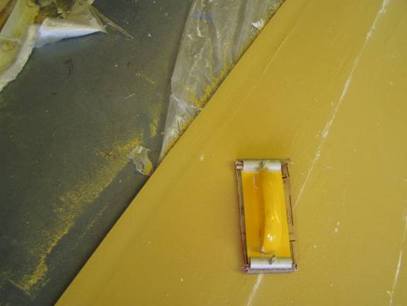
Where the ½” foam panels meet the ¼” panels,
the ½” foam panels need to be sanded into a ramp so there
is a smooth transition from the surface of the ½” panel
to the ¼” panel. This ramp should extend about an
inch and a half onto the ½” sheet. Be careful not
to sand into the ¼” foam. We need the full thickness. When
you are satisfied with inside surface of the rear fuselage panels, vacuum
them well.
Vacuum the panel surface before taping and glassing
The fiberglass will cover the entirety of the ½” panels
and will extend exactly 1” onto the ¼” panels. Refer
down a couple of photos to understand the layup schedule. Lay two
layers of masking tape lengthwise on the ¼” foam panels,
1” inside the interface between adjacent panels. The masking
tape does not stick well to the foam panels, so do not stretch it tight,
press it straight into the panel.
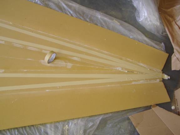
Masking tape Dams
Once the tape is secure mix up a batch
of thin slurry and slurry the ½” panels
and 1” of the ¼” panels. The layup a single
layer of BID on the 45 degree bias. This bias should be oriented
front to back.
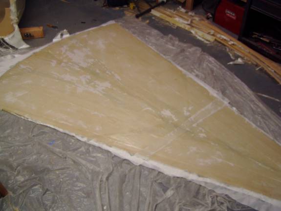
Fiberglass on inside of rear fuselage panels
Let the fiberglass partially cure, at least 12 hours. The glass
is easer to cut if it is still in the green state. Cut the fiberglass
free of the panels at the intersection of the fiberglass and the masking
tape. Remove the tape. Be very careful not to cut into the
foam panel. We need the integraty of the foam across the fiberglass
edge.
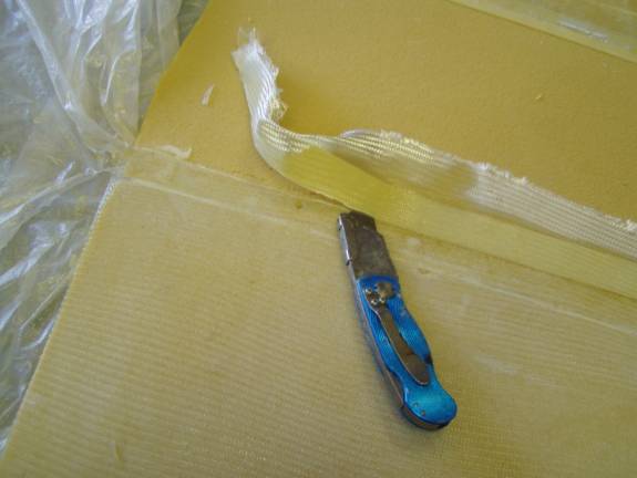
Cut the fiberglass at the tape edge
Completed Rear Fuse Inside Glass
Flip the large panel over and prepare the outside as you did the inside. Sand down any micro that may have oozed from the joints and fill any cracks with micro.
Use a sanding block to gently sand a joggle all the way around the outside of the large panel. The joggle should be about 2" along the long side; the side that will end up being the top edge of the rear fuselage side. The joggle should be about 3 inches along the forward edge of the outboard most panels; the edge that will end up being the forward edge of the rear fuselage section sides. The joggle should be about 4" along the forward edge that will end up being the front bottom edge of the rear fuse section. The reason that the joggle is larger on the front bottom edge is that we will eventually removing about 2" of material here and want to end up with a 2" joggle left. You can look ahead a few photos to the part describing the trimming of the rear fuselage section to better understand the final result.
Adding a joggle into the foam
Give the outside panel a final once over. The outside surface of the aircraft will only be as smooth as this panel is now. Finally vacuum the surface and prepare to glass.
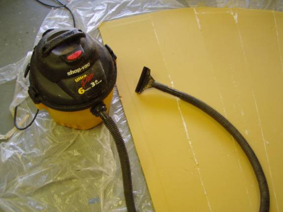
Again, vacuum the surface before slurry and glass
We will be fiberglassing the rear panel in one layer of UNI with the major fibers running front to back of the aircraft, then one layer of BID with the 45 degree bias running front to back. This will be a large layup so prepare well. Cut, bag and mark all of your glass. Have plenty of gloves, brushes, epoxy and micro on hand.
Go for it.
Completed rear layup covered in peel ply
Folding the Rear Fuselage Section
Let the panel fully cure. Remove the peel ply and inspect your handywork. We are now ready to fold it into a tail cone. Clearly mark the center line of the panel as shown in the next photo. Grab the E former used to make the forward fuselage half and make a mark on the cross member 2X2, as shown in the following photo.
Secure the top 2X2 cross member to the panel with two 2.5” sheet
rock screws and fender washers. Space the former about 2” from
the edge of the panel. Now gently fold the fuselage sides down
and secure to the side members of the former. The former should
be evenly spaced from the fuselage sides, again about 2” from the
edge. The photo after next shows the correct placement of this
former. Secure the tail end of the fuselage sides to each other
with a ½” spacer block. The fuselage sides will have
a slight twist in them as they transition from the tilted sides at the
front to vertical sides at the rear.
Preparing to fold the panel
Out next job is to make the cut at the front of the fuselage and the rear of the fuselage. First we need to level the rear fuselage tail cone up side down with respect to the level line of the fuselage. Flip the tail cone over and orient it as in the following photo. The forward side of the tail cone is a couple of inches long and we will need to cut this off. Make a mark 2” back from the front edge of the tail cone on the lower front edge of the at the aft end of the fuselage side. This will be our second point. Reference the following drawing to understand the points orientation with each other. We will use a laser level to place the aft edge of the fuselage 6 inches lower than the front edge of the fuselage. That is, make a third point on the fuselage side, 6 inches above the point at the aft end of the fuselage. Then a line passing through the first point and this third point should be level. Use a laser level to make this so. Use a carpenter’s level to level the fuselage side to side.
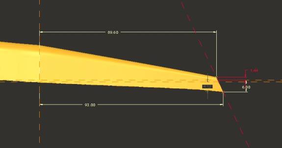
Leveling the rear fuselage section
Using a squar,e draw a line on the bottom of the fuselage, two inches back from the front edge. This line should be perpendicular to the center line. In the following photo, the knife is cutting the line I’m speaking of. Use the laser level with a vertical beam to continue this line around the radius and down the side of the fuselage. The knife is cutting this line in the photo after next.
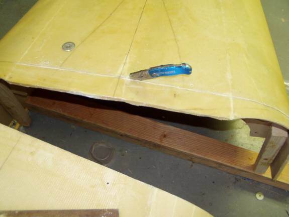
Trimming the front side of the Rear Fuselage
Once the forward edge of the rear fuselage section is defined, use a
razor blade to cut away the extra material Use multiple strokes
of the razor blade to cut cleanly through your pencil marks.
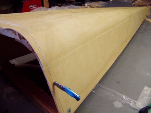
Trimming the Fuselage Rear Section
We are now ready to join the front and rear fuselage sections.