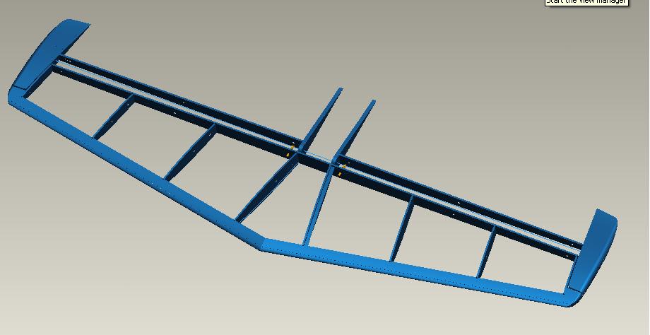
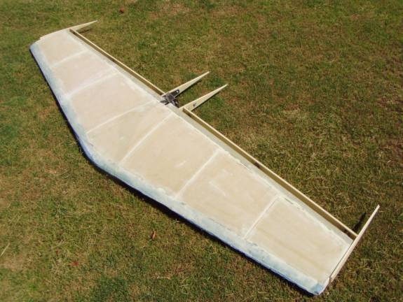
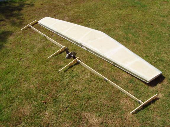
There are two control surfaces that constitute the elevator in the Super2. they are connected together with a control weldment to the elevator bellcrank. Each control surface is constructed from an elevator spar, a driving rib and a wing tip rib. A foam block then fills the space between and are glassed over in carbon fiber. The elevator ribs should have been cut out earlier. these are made using the patterns found on the download page from 1/4" 4.5 lb. last-a-foam glassed on both sides with 1 layer BID.
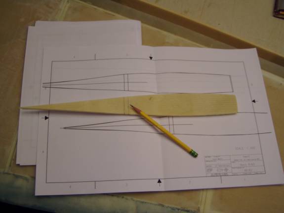
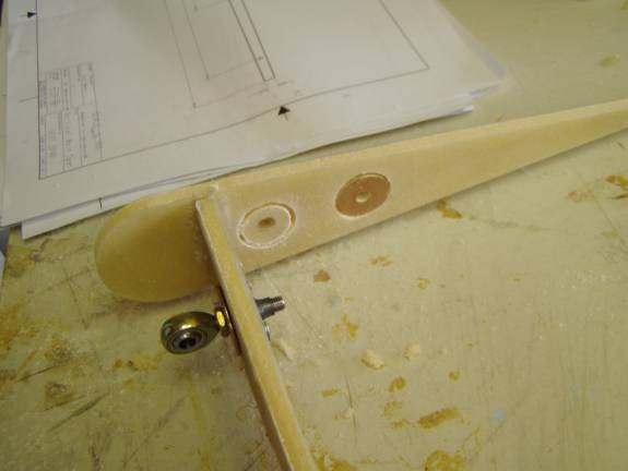
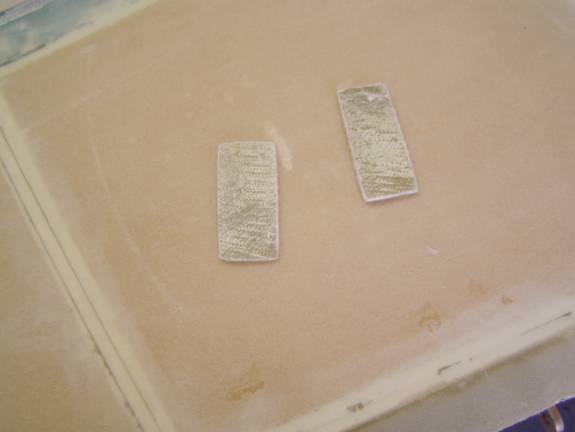
Copy the spar location on all four elevator ribs as shown above. These ribs will be attached to each end of the spar, but first we need to attach the hinges to the elevator spars.
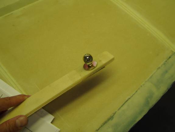
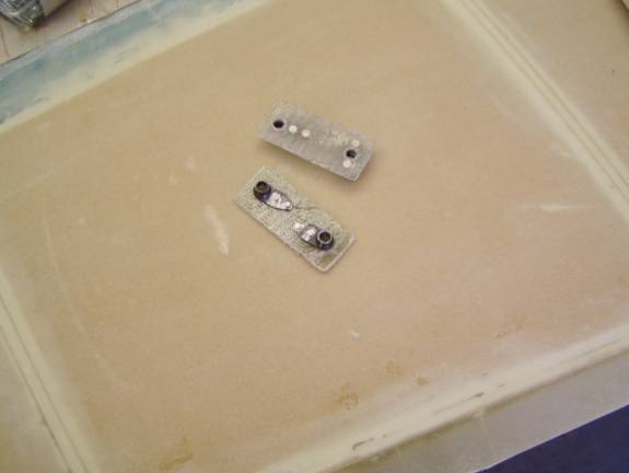
Drill out the hinge holes thought the elevator spars slightly over sized. We want the rod end to have play so we can position the nut plates precisly.. One side of the spar was reinfored with two BID, this side points aft. Take an Arrora MM4 rod end and install a MS half height lock nut all the way on and tighten. Install a MM shoulder washer.
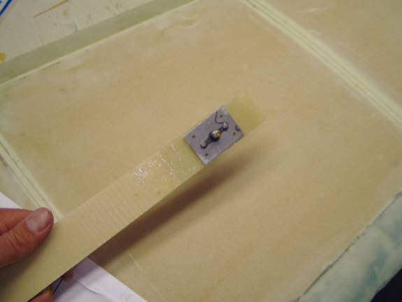
Use a nut plate to secure the rod end. Make sure the side of the spar with the double BID reinforcement mates tot the nut plate. tighten unti there is still alittle play.
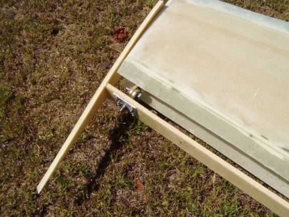
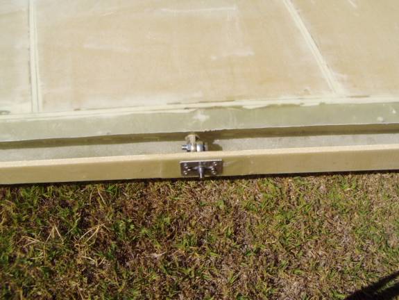
Install the elevator spars to the horizontal stabilizer. You may use inexpensive hardware like the 1/4" bolts shown laying on the table for initial fit, but we will use AN hardware and locking nuts for final assembly. If the spar buckles or is not centered, enlarge the holes abit. Insure that the spar is centered up and down.
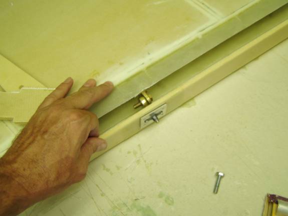
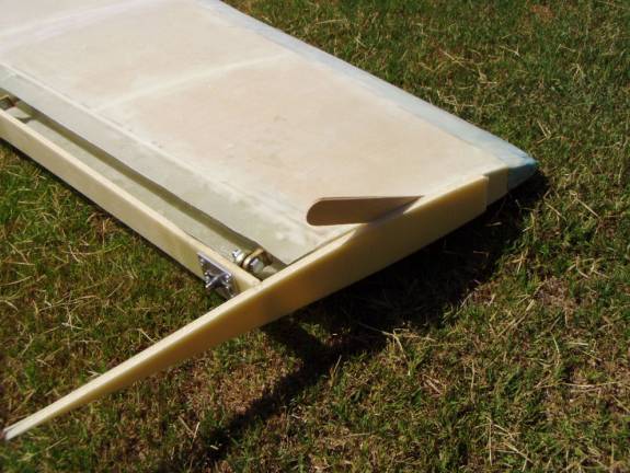
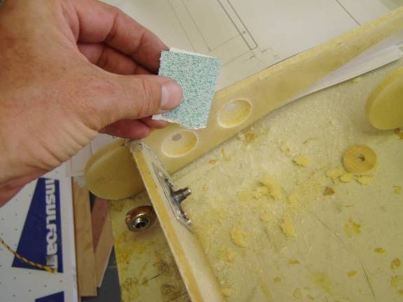
Insure that the horizontal stab end rib is sanded smoth. this edge will be used to define the proper location for the elevator tip rib. Use a 1/8" spacer between the horizontal stab end and the elevator and using the pencil marks on the rib to align it with the spar, tape the rib into position. The spar may need to trimmed to mate with the angled rib. When the spar is trimmed and centered, rivet the nutplates into position with pop rivets. Tighten the arrora rod end bearings into the nut plates. They should be tightened 1/2 turn past where they first impact the rear spar.
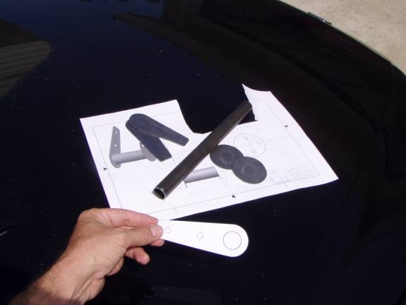
At this point we will need the elevator control weldments. Use the print to fabricate the individual parts for the elevator control weldment from 4130 steel. Also fabricate the elevator control horn from 1/8" sheet aluminum.
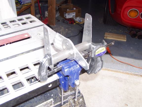
Jig the welments and insure they are square then weld.
The end ribs can be attached first. They only need to be tacked into place at this stage. the easiest way to accomplish this is to use CA glue. Apply the CA to both surfaces, then align the parts precisley with gloved fingers, then spray with CA accelerator.
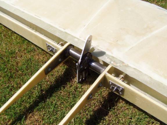
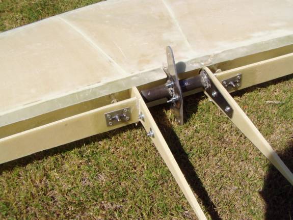
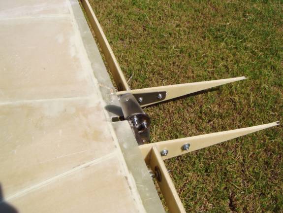
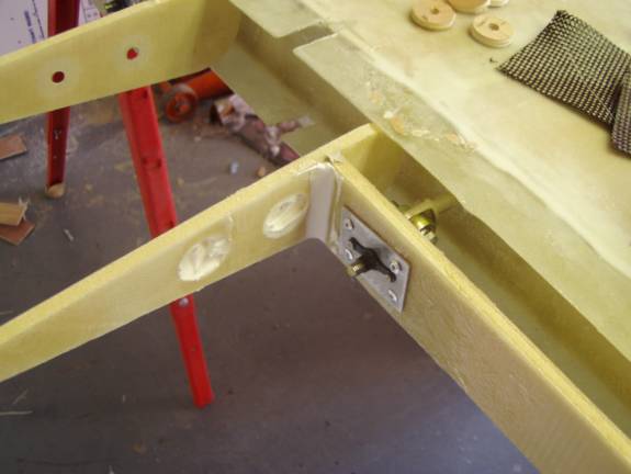
Cut a notch in the top and bottom rear flange on the horizontal stabilizer exactly in the middle. this notch will be used to locate the elevator control belcrank. Bolt the two driving ribs, elevator weldments and elevator bellcrank together as a unit. The multiple holes in the bellcrank face downward. Insure that this assembled unit is square, if not tweek the weldments until it is so. Using the two driving ribs bolted together in this way, trim the two elevator spars so the rib assembly is located exactly in the center of the horizontal spar. Line the driving ribs up with the spar using the pencil marks on driving ribs. There should be a small gap between the driving ribs and the rear flanges. When everything is aligned, tack the driving ribs into place against the spars.
Insure that the entire assembly is square and there is proper spacing between the tip ribs and the stab.
There
There
Dissasemble the elevator, being very careful as it is delicate.
Install hardpoints on the inside of the driving rib as was done for the spars.
Installing these hardpoints would have been easier if it were done before the ribs were attached to the spar.
While you are installing the hardpoints, if there is extra micro, add radii to the front and back side of each spar where the two ribs are attached. We will be adding layers of carbon fiber to this joint.
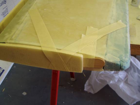
Once the hardpoints have cured, reinstall the elevator to the horizontal stab and secure the ribs into their proper position. Take your time because we are going to permanently attach the ribs to the spar. We do not want any twists out of square elements.
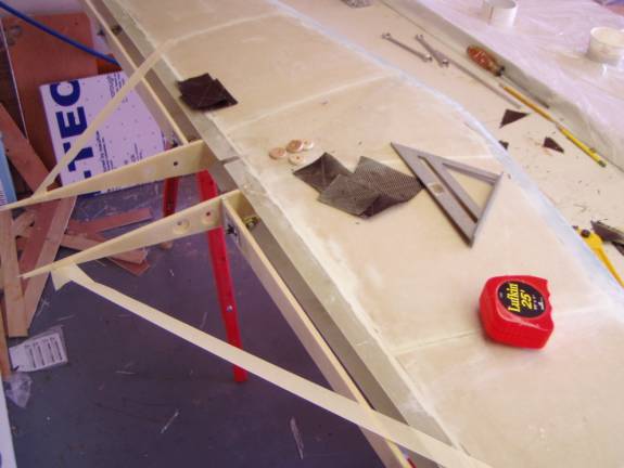
Do what ever is necessary to insure the ribs are square, here all I needed was a little tension provided by strips of masking tape. Use a square to insure proper alignment of the dirving ribs.
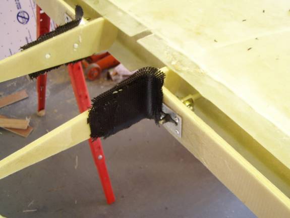
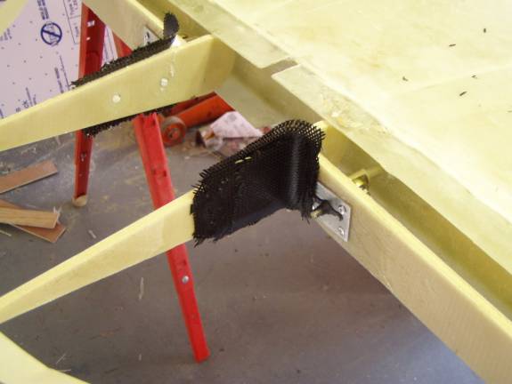
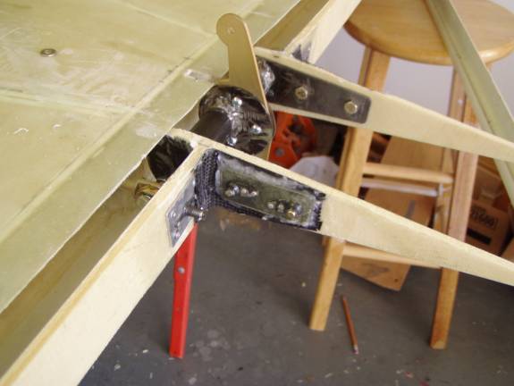
Add four layers of carbon fiber to the two outside joints of the spar to the driving rib and the tip rib. Use decreasing sizes of carbon so you have a feathered edge. The reason that carbon is used in these joints is because of the load carried by the driving rib.
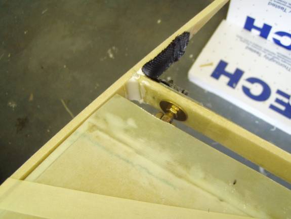
Here you can see the radius on the inside joint. This can not be glassed until the outside cures and the elevator is removed.

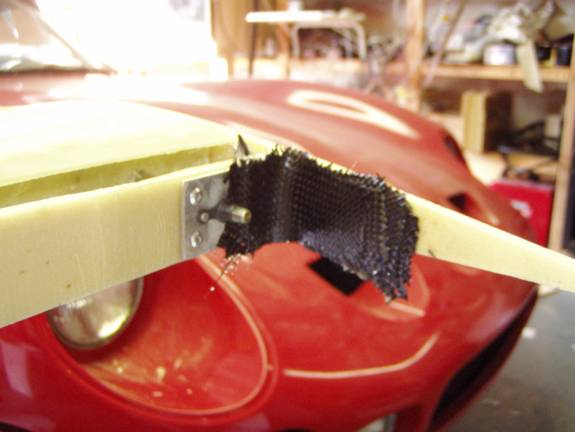
Use 4 layers of carbon fiber on the tip rib as well. this rib joint needs to be strong due the the counterbalance weight in the elevator tip.
Clamp the nut plates directly to the elevator control horn welement
and drill holes to match those in the weldment. Install bolts to hold
the nut plates in position as the rivet holes are drilled. then countersink
and rivet the nut plates in position. Mark the nut plates, right and
left. 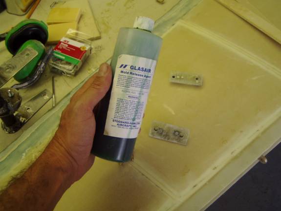
We will use a little mold release on the bolts and nut plates while
they are curing so as not to gum up our threads. 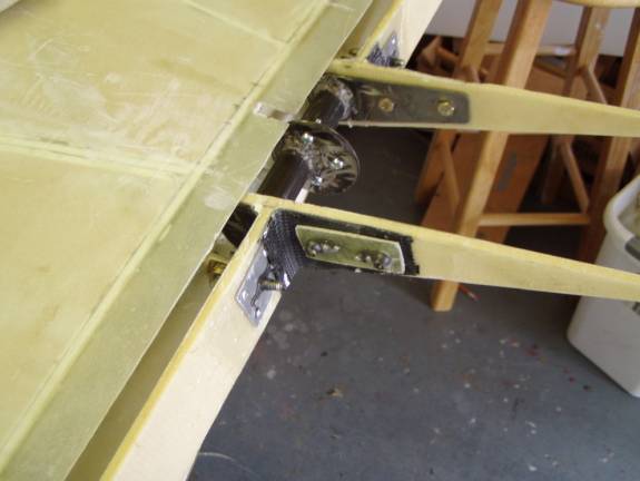
Attatch the welements to the elevators and insure the proper position of the entire assembly. Once you are happy with the position of everything prepare to attach the nut plates.
Sand and clean both surfaces and use a thick flox mixture to attach the nut plates. Why are we using fiberglass nutplates instead of aluminum nutplates? Carbon fiber and aluminum do not get along together--aluminum in contact with carbon fiber can corrode. But look the hinge nut plate is covered with carbon fiber in the photo above...good point.